
RAM 3500 Truck 2WD V10-8.0L VIN W HDC (2000)
together, a zero slippage condition could be obtained. A hydraulic piston was added to the turbine, and a friction material was added to the inside of
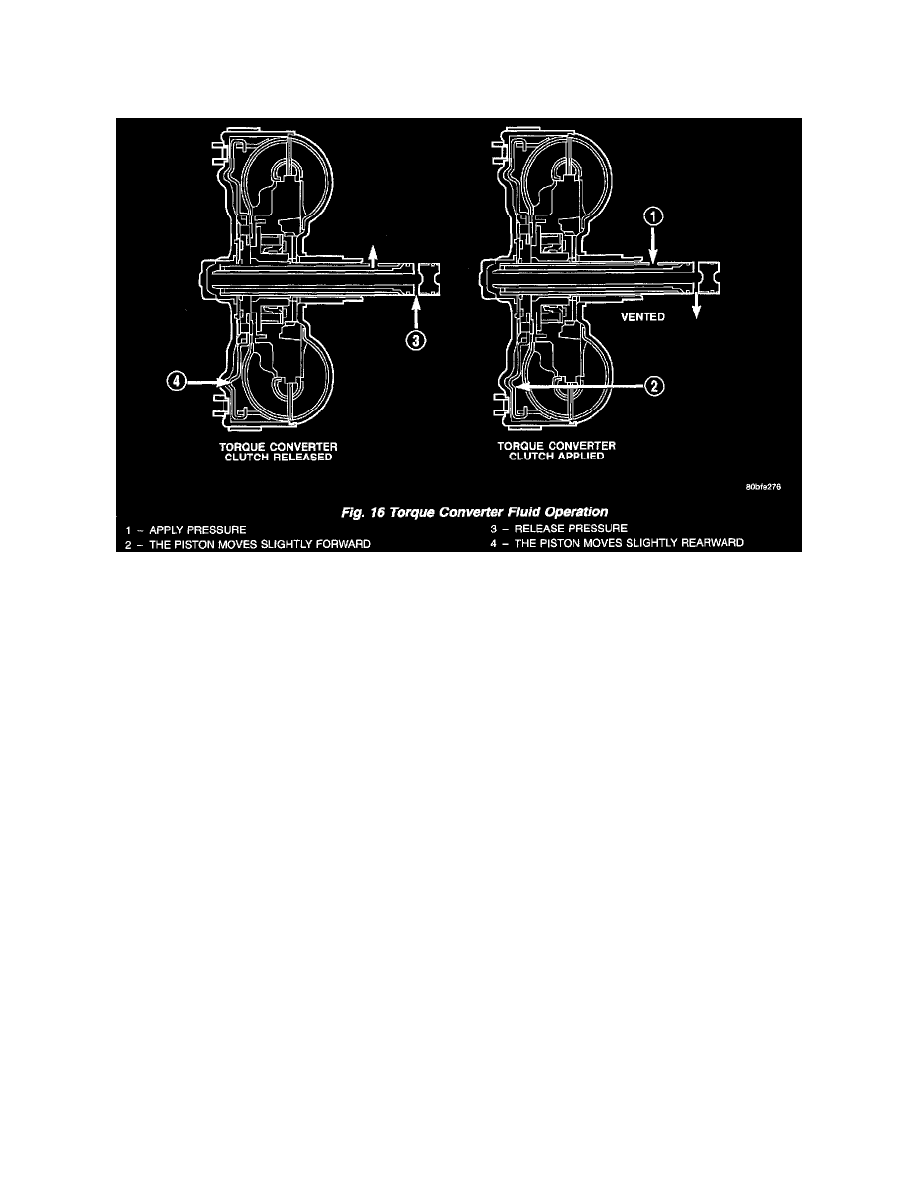
the front cover to provide this mechanical lock-up.
OPERATION
Fig. 16
The converter impeller (Fig. 16) (driving member), which is integral to the converter housing and bolted to the engine drive plate, rotates at engine
speed. The converter turbine (driven member), which reacts from fluid pressure generated by the impeller, rotates and turns the transmission input
shaft.
TURBINE
As the fluid that was put into motion by the impeller blades strikes the blades of the turbine, some of the energy and rotational force is transferred into
the turbine and the input shaft. This causes both of them (turbine and input shaft) to rotate in a clockwise direction following the impeller. As the fluid
is leaving the trailing edges of the turbine's blades it continues in a "hindering" direction back toward the impeller. If the fluid is not redirected before
it strikes the impeller, it will strike the impeller in such a direction that it would tend to slow it down.
STATOR