
RAM 3500 Truck 2WD V8-5.7L VIN D (2003)
5. Grasp the integrated power module with two hands and slide the assembly in the direction shown (Fig. 3) to free the module from its mounting
bracket. Position the assembly upside down to access the electrical connectors located on the bottom of the unit.
6. Disconnect the electrical connectors by depressing the locking tab and rotating the connector arm outboard, until the connector is free from the
module assembly. Be certain to pull the connectors straight off.
7. Position the integrated power module on a bench and remove the four front control module retaining screws.
8. Disconnect the front control module by pulling it straight off the integrated power module.
INSTALLATION
1. Connect the front control module by pushing it straight on the integrated power module electrical receptacle.
2. Install the four front control module retaining screws. Torque to 30 ± 5 in. lbs..
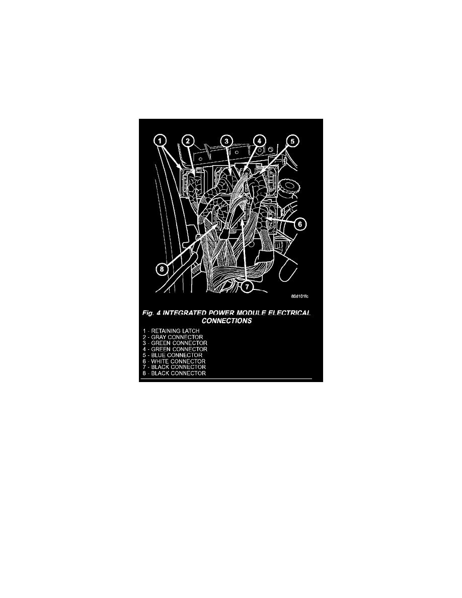
Fig.4 Integrated Power Module Electrical Connections
NOTE: Integrated power module electrical connectors are color coded to ease location reference (Fig. 4).
3. Connect the electrical connectors by pushing straight on and rotating the connector arm inboard, until the connector is firmly locked in place on
the module assembly.