
RAM 3500 Truck 2WD V8-5.7L VIN D (2003)
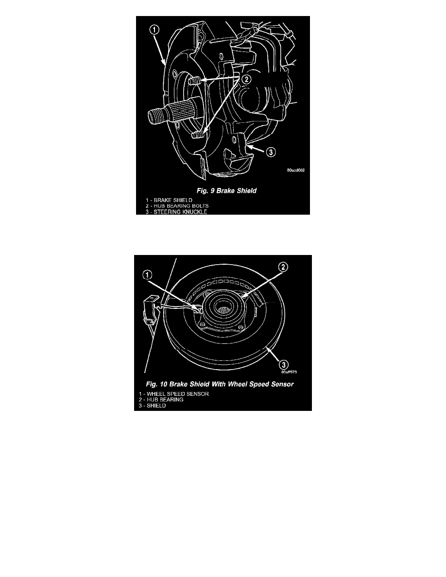
Fig. 9
6. Position the hub spacer and brake shield on bolts just installed in knuckle.
Fig. 10
NOTE: If the vehicle is equipped with a wheel speed sensor the brake shield must be positioned on the hub bearing.
7. Align the rotor hub with the drive shaft and start the shaft into the rotor hub splines.
NOTE: Position wheel speed sensor wire at the top of the knuckle if equipped.
8. Align the bolt holes in the hub bearing flange with the bolts installed in the knuckle. Then thread the bolts into the bearing flange far enough to
hold the assembly in place.
9. Install the remaining bolts. Tighten the hub/bearing bolts to 202 Nm (149 ft. lbs.).
10. Install the washer and axle nut and tighten a beginning torque of 179 Nm (132 ft. lbs.).
11. Rotate the axle 5 to 10 times to seat the hub bearing.
12. Tighten to a final torque of 356 Nm (263 ft. lbs.).
13. Align the axle nut to the next forward cotter pin hole and install a new cotter pin in the axle nut.
14. Install the brake caliper.
15. Install the sensor wire to the steering knuckle and frame and if equipped. Connect the wheel speed sensor wire under the hood.