
RAM 3500 Truck 4WD L6-5.9L DSL Turbo VIN C (2002)
Camshaft Gear
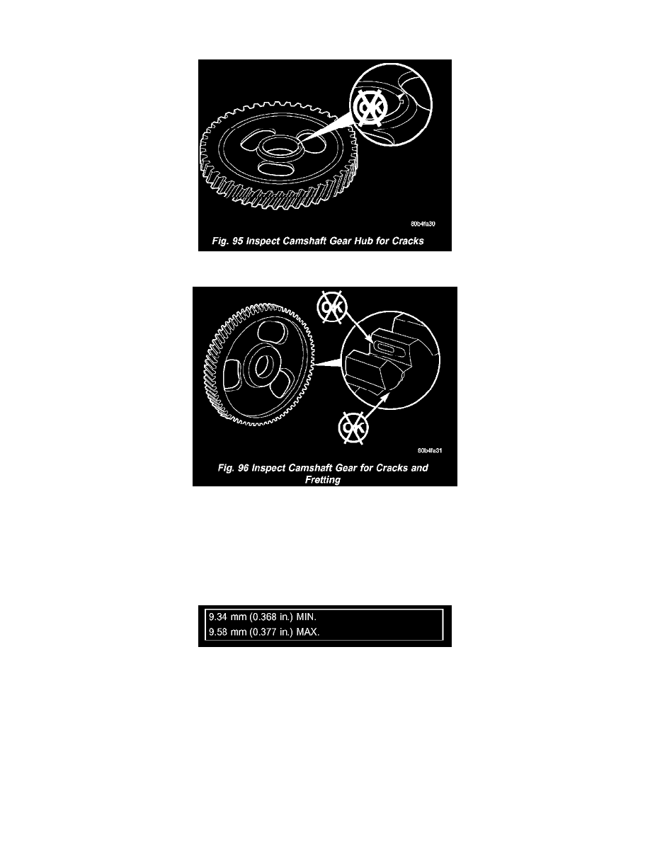
Figure 95
Figure 96
Inspect the camshaft gear for cracks (gear and hub) (Fig. 95), and chipped/broken/fretted teeth (Fig. 96). If replacement is necessary, Refer to
CAMSHAFT BEARING, SERVICE AND REPAIR.
Thrust Plate
Inspect the camshaft thrust plate for excessive wear in the camshaft contact area. Measure thrust plate thickness using the CAMSHAFT THRUST
PLATE THICKNESS CHART. Replace any thrust plate that falls outside of these specifications:
CAMSHAFT THRUST PLATE THICKNESS CHART
INSTALLATION - CAMSHAFT
1. Lubricate the camshaft bushing and bores with fresh engine oil or suitable equivalent.
2. Liberally coat the camshaft lobes, journals, and thrust washer with fresh engine oil or suitable equivalent.
CAUTION: When installing the camshaft (Fig. 91), DO NOT push it in farther than it will go with the thrust washer in place. Pushing it too far
can dislodge the plug in the rear of the camshaft bore and cause an oil leak.
3. Install the camshaft (Fig. 91) and thrust plate. Align the timing marks as shown in (Fig. 89).
4. Install the thrust plate bolts and tighten to 24 Nm (18 ft. lbs.) torque.