
RAM 3500 Truck 4WD L6-5.9L DSL Turbo VIN C (2002)
2. Thoroughly clean fuel injector cylinder head bore with special Cummins wire brush tool or equivalent (Fig. 24). Blow out bore hole with
compressed air.
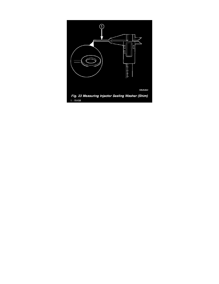
Fig.23 Measuring Injector Sealing Washer (Shim)
3. The bottom of fuel injector is sealed to cylinder head bore with a copper sealing washer (shim) of a certain thickness. A new shim with correct
thickness must always be re-installed after removing injector. Measure thickness of injector shim (Fig. 23). Shim Thickness: 1.5 mm (.060")
4. Install new shim (washer) to bottom of injector (Fig. 22). Apply light coating of clean engine oil to washer. This will keep washer in place during
installation.
5. Install new O-ring to fuel injector. Apply small amount of clean engine oil to O-ring.
6. Note fuel inlet hole on side of fuel injector. This hole must be positioned towards injector connector tube. Position injector into cylinder head bore
being extremely careful not to allow injector tip to touch sides of bore. Press fuel injector into cylinder head with finger pressure only Do not use
any tools to press fuel injector into position. Damage to machined surfaces may result.
7. Position fuel injector hold down clamp into shouldered bolt while aligning slot in top of injector into groove in bottom of clamp. Tighten opposite
clamp bolt (Fig. 18) to 10 Nm (89 in. lbs.) torque.
8. Install new O-ring to fuel injector connector tube. Apply small amount of clean engine oil to O-ring.
9. Press injector connector tube into cylinder head with finger pressure only. Do not use any tools to press tube into position. Damage to machined
surfaces may result.
10. Connect high-pressure fuel lines. Refer to High-Pressure Fuel Lines Removal/Installation. The fuel line fitting torque is very critical. If fitting is
under torqued, the mating surfaces will not seal and a high-pressure fuel leak will result. If fitting is over torqued, the connector and injector will
deform and also cause a high-pressure fuel leak. This leak will be inside cylinder head and will not be visible resulting in a possible fuel injector
miss and low power.
11. Install valve cover.
12. (1f necessary) install intake manifold air heater assembly. Refer to Intake Manifold Air Heater Removal/Installation.
13. (1f necessary) install engine lifting bracket. Tighten 2 bolts to 77 Nm (57 ft. lbs.) torque.
14. Connect negative battery cables to both batteries.
15. Bleed air from high pressure lines.