
RAM 3500 Truck 4WD L6-5.9L DSL Turbo VIN C (2002)
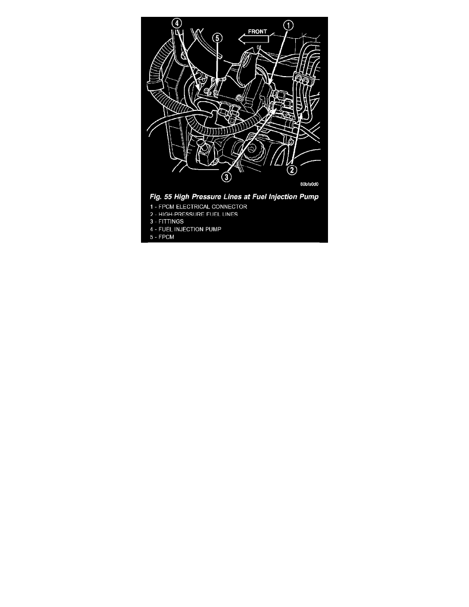
Fig.55 High Pressure Lines At Fuel Injection Pump
17. Loosen high-pressure line fittings at injection pump (Fig. 55) beginning with cylinders 1, 2 and 4.
18. Loosen high-pressure lines at cylinder head for cylinders 1, 2 and 4 (Fig. 54).
19. Carefully remove front line bundle from engine. Do not bend lines while removing. While removing front line bundle, note line position.
20. Loosen high-pressure lines at injection pump beginning with cylinders 3, 5 and 6.
21. Loosen high-pressure lines at cylinder head for cylinders 3, 5 and 6 (Fig. 54).
22. Carefully remove rear line bundle from engine. Do not bend lines while removing. While removing rear line bundle, note line position.
INSTALLATION
High-pressure lines are used between the fuel injection pump and the fuel injectors only. All highpressure fuel lines are of the same length and inside
diameter. Correct high-pressure fuel line usage and installation is critical to smooth engine operation.
CAUTION: Be sure that the high-pressure fuel lines are installed in the same order that they were removed.
1. Lubricate threads of injector line fittings with clean engine oil.
2. Loosen, but do not remove, all fuel line support bracket bolts.
3. Install rear injection line bundle beginning with cylinder head (fuel injector) connections, followed by injection pump connections. Tighten all
fittings finger tight.
4. Tighten fittings at fuel injector ends for cylinders number 6 and 5 to 38 Nm (28 ft. lbs.) torque.
Do not tighten number 3 line at this time. It will be tightened during bleeding procedure.
5. Tighten 3 fittings at fuel injection pump ends to 24 Nm (18 ft. lbs.) torque.
6. Install front injection line bundle beginning with cylinder head (fuel injector) connections, followed by injection pump connections. Tighten all
fittings finger tight.
7. Tighten fitting at fuel injector end for cylinder number 2 to 38 Nm (28 ft. lbs.) torque. Do not tighten lines number 1 or 4 at this time. They will be
tightened during bleeding procedure.
8. Tighten remaining 3 fittings at fuel injection pump ends to 24 Nm (18 ft. lbs.) torque.
9. Install fuel line support bracket bolts to intake manifold and tighten to 24 Nm (18 ft. lbs.) torque.
CAUTION: Be sure fuel lines are not contacting each other or any other component. Noise will result.
10. Install engine lifting bracket at rear of intake manifold. Tighten 2 bolts to 77 Nm (57 ft. lbs.) torque.
11. Install cable bracket housing/cable assembly and tighten 3 mounting bolts to 24 Nm (18 ft. lbs.) torque.
12. Clean any old gasket material below and above intake manifold air heater element block. Also clean mating areas at intake manifold and air intake
housing.
13. Using new gaskets, position intake manifold air heater element block to engine.
14. Install air intake housing and position ground cable. Install 4 mounting bolts and tighten to 24 Nm (18 ft. lbs.) torque.