
RAM 3500 Truck 4WD L6-6.7L DSL Turbo (2008)
Wheel Bearing: Service and Repair
Front Hub / Bearing - Installation
4X4 - Independent Front Suspension
4X4
1. Install the brake dust shield (2).
2. Install the hub/bearing (1) into the steering knuckle (3) and tighten the bolts to 163 Nm (120 ft. lbs.).
3. Install the brake rotor and caliper See: Brakes and Traction Control/Disc Brake System/Brake Rotor/Disc/Service and Repair/Removal and
Replacement/Brake Rotor - Installation .
4. Install the ABS wheel speed sensor if equipped See: Brakes and Traction Control/Antilock Brakes / Traction Control Systems/Wheel Speed
Sensor/Service and Repair/Front Wheel Speed Sensor - Installation .
5. Install the upper ball joint nut to the steering knuckle and tighten to 54 Nm (40 ft. lbs.) (on 1500 series only an additional 90° turn).
6. Install the tie rod end nut to the steering knuckle and tighten to 61 Nm (45 ft. lbs.) then an additional 90°.
7. Install the halfshaft nut and tighten to 251 Nm (185 ft. lbs.).
8. Install the wheel and tire assembly See: Service and Repair/Removal and Replacement .
9. Remove the support and lower vehicle.
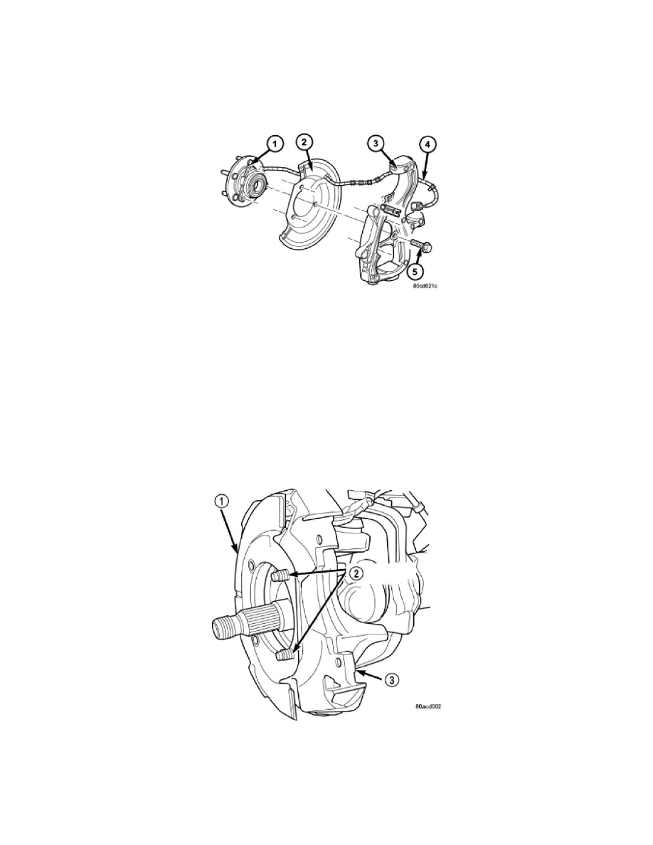
2500 & 3500 - 4WD - Link/Coil
2500 & 3500 - 4WD
1. Position the brake shield (1) on bolts.
2. Install the hub/bearing to the knuckle. Tighten the hub/bearing bolts (2) to 202 Nm (149 ft. lbs.
3. Install the hub nut and tighten to 356 Nm (263 ft. lbs.).
4. Install the wheel speed sensor to the hub. See: Brakes and Traction Control/Antilock Brakes / Traction Control Systems/Wheel Speed
Sensor/Service and Repair/Front Wheel Speed Sensor - Installation .
5. Install the disc brake rotor. See: Brakes and Traction Control/Disc Brake System/Brake Rotor/Disc/Service and Repair/Removal and
Replacement/Brake Rotor - Installation .