
RAM 3500 Truck 4WD V10-8.0L VIN W (1997)
e.
Using a prybar, reposition the rear axle to obtain a 0.0° +/- 0.2° of thrust angle.
NOTE:
MAKE SURE THE LEAF SPRING CENTERBOLT IS BEING LOCATED IN THE ALIGNMENT HOLE IN THE SPRING SPACER SEAT,
NOT IN THE VOID OF THE SPRING SEAT.
f.
Tighten the spring clamp nuts until they force the plate flush against the axle tube.
g.
Remove axle supports and lower the vehicle so that the weight of the vehicle is supported by the tires.
h.
Tighten the spring clamp retaining nuts to 163 Nm (120 ft. lbs.) of torque.
CAUTION:
DO NOT OVER TORQUE THE SPRING CLAMP RETAINING NUTS. EXCEEDING 163 Nm (120 FT. LBS) OF TORQUE WILL CAUSE
DAMAGE TO THE SPRING CLAMP BOLTS
i.
Verify rear thrust angle. Repeat steps a through I until rear thrust angle is within specifications.
Correcting For Rear Camber or Toe
3.
CORRECTING FOR REAR CAMBER OR TOE
a.
If rear toe and/or camber are out of specifications, but thrust angle is within specifications, replace the rear axle assembly. Refer to the
appropriate Service Manual for information regarding rear differential service.
Correcting For Front Caster/Camber
4.
CORRECTING FOR FRONT CASTER/CAMBER
a.
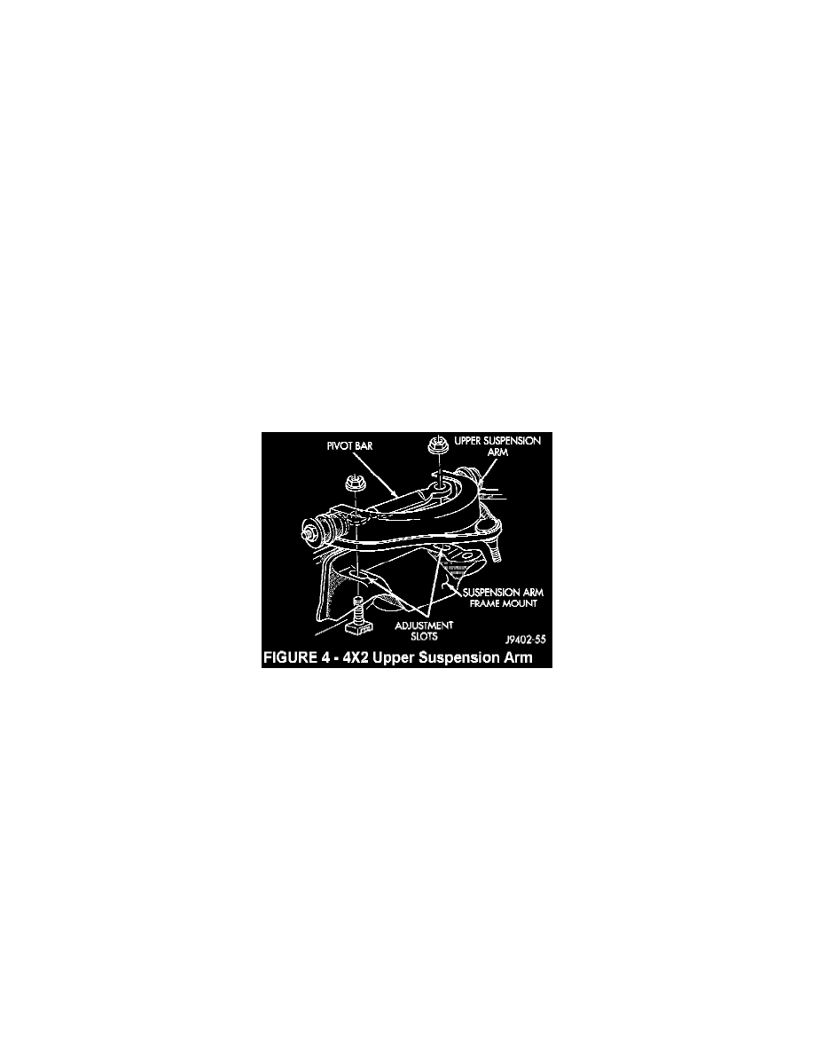
If the vehicle is a 4X2 and front caster or camber require adjustment, move the pivot bar located on the top of the upper suspension arm
(Figure 4). Refer to the 1997 Dodge Ram Service Manual (Publication Number 81-37-7108), pages 2-1 through 2-7 for proper alignment
procedures.
b.
If the vehicle is equipped with a Dana 44 front axle (all 1500 series 4X4 and 7500 lb GVW 2500 series 4X4), caster and toe are the only
front alignment angles that can be altered. Refer to the 1997 Dodge Ram Service Manual (Publication Number 81-37-7108), pages 2-1
through 2-7 for proper alignment procedures.