
RAM 3500 Truck 4WD V10-8.0L VIN W (1997)
Ignition Switch: Initial Inspection and Diagnostic Overview
The content of this article reflects changes called for in TSB 26-01-97.
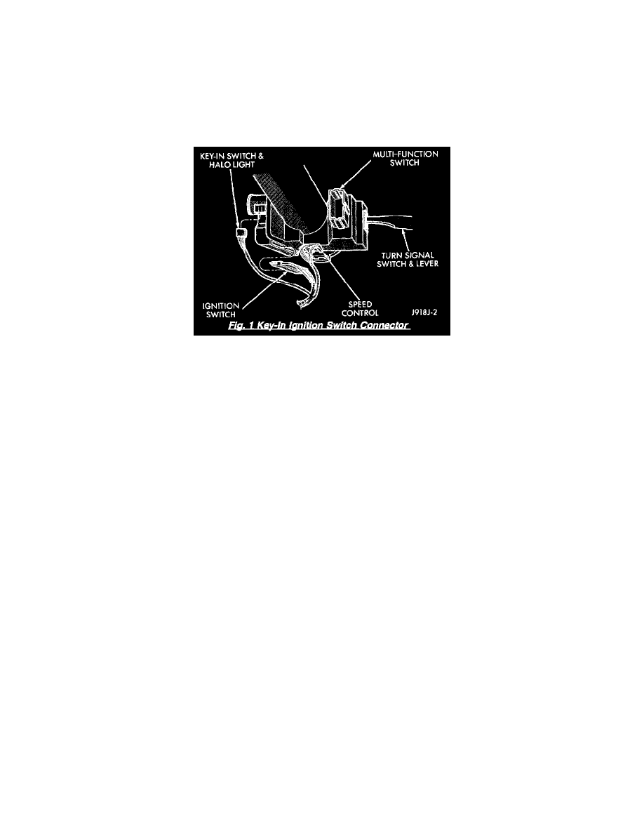
Key-In Ignition Switch
WARNING: ON VEHICLES EQUIPPED WITH AIRBAGS, REFER TO RESTRAINTS SYSTEMS / AIR BAG SYSTEMS BEFORE
ATTEMPTING ANY STEERING WHEEL, STEERING COLUMN, OR INSTRUMENT PANEL COMPONENT DIAGNOSIS OR
SERVICE. FAILURE TO TAKE THE PROPER PRECAUTIONS COULD RESULT IN ACCIDENTAL AIRBAG DEPLOYMENT
AND POSSIBLE PERSONAL INJURY. See: Restraint Systems/Air Bag Systems
1. Disconnect and isolate the battery negative cable. Remove the steering column shrouds. Unplug the key-in ignition switch wire harness
connector from the ignition switch.
2. Check for continuity between the key-in switch sense circuit and the left front door jamb switch sense circuit terminals of the key-in ignition
switch. There should be continuity with the key in the ignition lock cylinder and no continuity with the key removed from the ignition lock
cylinder If OK go to 3. If not OK, replace the faulty ignition switch.
3. Open the driver door. Check for continuity between the left front door jamb switch sense circuit cavity of the key-in ignition switch wire
harness connector and a good ground. There should be continuity. If OK, go to 4. If not OK, repair the open circuit to the driver door jamb
switch as required.
4. Unplug the buzzer module from the fuseblock module receptacle. Check for continuity between the key-in switch sense circuit cavity of the
buzzer module receptacle in the fuse block module and a good ground. There should be no continuity. If OK, go to 5. If not OK, repair the
short circuit as required.
5. Check for continuity between the key-in switch sense circuit cavities of the key-in ignition switch wire harness connector and the buzzer
module receptacle in the fuse block module. There should be continuity. If OK, test the buzzer module. If not OK, repair the open circuit as
required. See: Instrument Panel, Gauges and Warning Indicators/Audible Warning Device Control Module/Testing and Inspection