
RAM 3500 Truck 4WD V8-59L VIN Z LDC (2000) - Seat Heater Relay Location
Seat Heater Relay: Testing and Inspection
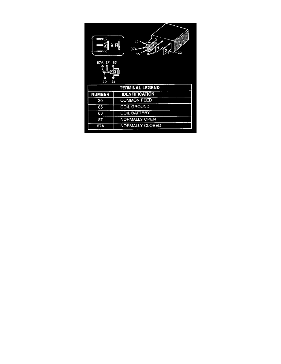
Heated Seat Relay
The heated seat relay is located in the Junction Block (JB) on the left end of the instrument panel in the passenger compartment of the vehicle.
WARNING: ON VEHICLES EQUIPPED WITH AIRBAGS, DISABLE THE AIRBAG SYSTEM BEFORE ATTEMPTING ANY STEERING
WHEEL, STEERING COLUMN, OR INSTRUMENT PANEL COMPONENT DIAGNOSIS OR SERVICE. DISCONNECT AND ISOLATE
THE BATTERY NEGATIVE (GROUND) CABLE, THEN WAIT TWO MINUTES FOR THE AIRBAG SYSTEM CAPACITOR TO
DISCHARGE BEFORE PERFORMING FURTHER DIAGNOSIS OR SERVICE. THIS IS THE ONLY SURE WAY TO DISABLE THE
AIRBAG SYSTEM. FAILURE TO TAKE THE PROPER PRECAUTIONS COULD RESULT IN ACCIDENTAL AIRBAG DEPLOYMENT
AND POSSIBLE PERSONAL INJURY.
RELAY TEST
1. Remove the heated seat relay from the JB. Refer to Heated Seat Relay removal procedures.
2. A relay in the de-energized position should have continuity between terminals 87A and 30, and no continuity between terminals 87 and 30. If OK,
go to Step 3. If not OK, replace the faulty relay.
3. Resistance between terminals 85 and 86 (electromagnet) should be 75 +/- 5 ohms. If OK, go to Step 4. If not OK, replace the faulty relay.
4. Connect a battery to terminals 85 and 86. There should now be continuity between terminals 30 and 87, and no continuity between terminals 87A
and 30. If OK, perform the Relay Circuit Test that follows. If not OK, replace the faulty relay.
RELAY CIRCUIT TEST
1. The relay common feed terminal cavity (30) is connected to battery voltage and should be hot at all times. If OK, go to Step 2. If not OK, repair
the open circuit to the fused B(+) fuse in the Power Distribution Center (PDC) as required.
2. The relay normally closed terminal (87A) is connected to terminal 30 in the de-energized position, but is not used for this application. Go to Step
3.
3. The relay normally open terminal (87) is connected to the common feed terminal (30) in the energized position. This terminal supplies battery
voltage to the heated seat module. There should be continuity between the cavity for relay terminal 87 and the B(+) to heated seat module circuit
cavity of the heated seat module wire harness connector at all times. If OK, go to Step 4. If not OK, repair the open B(+) to heated seat module
circuit to the heated seat module as required.
4. The coil battery terminal (86) is connected to the electromagnet in the relay. It is connected to battery voltage and should be hot at all times. Check
for battery voltage at the cavity for relay terminal 86. If OK, go to Step 5. If not OK, repair the open circuit to the fused B(+) fuse in the PDC as
required.
5. The coil ground terminal (85) is connected to the electromagnet in the relay. It is grounded by the premium version of the Central Timer Module
(CTM) in response to an engine speed message received over the Chrysler Collision Detection (CCD) data bus from the Powertrain Control
Module (PCM) when the engine is running. Check for continuity between the cavity for relay terminal 85 and the heated seat relay control circuit
cavity of the CTM wire harness connector. There should be continuity at all times. If OK, use a DRB III scan tool and the proper diagnostic
procedures to test the operation of the CTM and CCD data bus. If not OK, repair the open heated seat relay control circuit as required.
For addtional testing please refer to Powertrain Management/Computers and Controls/Body Control Module/Testing and Inspection/ See: Body
Control Systems/Central Timer Module/Testing and Inspection