
RAM 3500 Truck 4WD V8-5.9L VIN Z LDC (2000)
Seat Heater Thermostat: Description and Operation
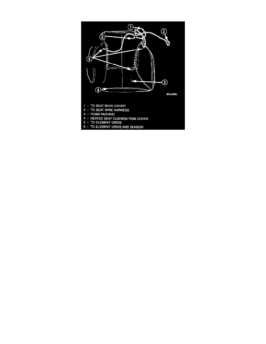
Heated Seat Cushion Trim Cover
HEATED SEAT ELEMENT AND SENSOR
Vehicles equipped with the optional heated seat system have two sets of electrically operated heating element grids located in each outboard
seating position of the front seat, one set for the seat cushion and the other set for the seat back. Each of the heated seat element grids consists of a
single length of resistor wire that is routed in a zigzag pattern and captured between the leather trim cover and the foam rubber backing on the
underside of its respective seat cushion trim cover and seat back trim cover assembly. Short pigtail wires with connectors are soldered to each end
of each resistor wire element grid, which connect all of the element grids for each seating position to each other in series with the heated seat
module through the seat wire harness.
One temperature sensor is used for each outboard seating position of the front seat, and it is located in the center insert area of the seat cushion
cover. The heated seat sensors and their pigtail wires are also captured between the leather trim cover and the foam rubber backing on the
underside of their respective seat cushion trim cover assemblies. The heated seat sensors are Negative Thermal Coefficient (NTC) thermistors. The
sensors for both front seats receive a voltage feed from a single output of the heated seat module, but the module receives individual sensor inputs
from the driver side and passenger side sensors.
The heated seat elements and sensors cannot be repaired. If damaged or faulty, the front seat cushion trim cover or front seat back trim cover
assembly must be replaced. Refer to Front Seat Cushion Cover - Quad Cab or Front Seat Back Cover - Quad Cab removal and installation
procedures.
One end of the heated seat element resistor wire is connected to a ground feed at all times through a splice in the heated seat module ground
circuit. Battery current is directed to the other end of the heated seat element resistor wire by the energized N-channel Field Effect Transistor
(N-FET) located within the heated seat module. The heated seat module will energize the N-FET only when the heated seat switch is in the Low or
High position and the heated seat sensor indicates that the seat cushion surface temperature is below the selected (Low or High) temperature set
point. As electrical current passes through the heating element grid, the resistance of the wire used in the element disperses some of that electrical
current in the form of heat. The heat produced by the heated seat element grid then radiates through the underside of the seat cushion and seat back
trim covers, warming the seat cover and its occupant.
The resistance of the heated seat sensor increases and decreases as the surface temperature of the seat cushion cover changes. The heated seat
module supplies each sensor with a voltage feed, then detects the sensor resistance by monitoring the voltage of the separate sensor return circuits.
The heated seat module compares the heated seat sensor resistance (seat cushion surface temperature) with the heated seat switch resistance (Low
or High set point) to determine when the heated seat element grids need to be cycled on or off in order to maintain the selected temperature set
point.