
RAM 3500 HD Truck 2WD L6-6.7L DSL Turbo (2008)
Clockspring Assembly / Spiral Cable: Removal and Replacement
Removal
REMOVAL
WARNING: To avoid serious or fatal injury on vehicles equipped with airbags, disable the Supplemental Restraint System (SRS) before
attempting any steering wheel, steering column, airbag, seat belt tensioner, impact sensor, or instrument panel component diagnosis or service.
Disconnect and isolate the battery negative (ground) cable, then wait two minutes for the system capacitor to discharge before performing
further diagnosis or service. This is the only sure way to disable the SRS. Failure to take the proper precautions could result in accidental
airbag deployment.
NOTE: Before starting this procedure, be certain to turn the steering wheel until the front wheels are in the straight-ahead position.
1. Place the front wheels in the straight ahead position.
2. Disconnect and isolate the battery negative cable.
3. Remove the driver airbag from the steering wheel. See: Air Bag/Service and Repair/Removal and Replacement/Driver Airbag - Removal .
4. Disconnect the steering wheel wire harness connectors from the upper clockspring connector receptacles.
CAUTION: Be certain that the screws that secure the steering wheel puller to the steering wheel are fully engaged in the steering wheel
armature without passing through the steering wheel and damaging the clockspring.
5. Remove the steering wheel from the steering column. See: Steering and Suspension/Steering/Steering Wheel/Service and Repair/Removal .
6. Remove the steering column opening cover from the instrument panel. See: Body and Frame/Interior Moulding / Trim/Dashboard / Instrument
Panel/Service and Repair/Steering Column Opening Cover - Removal .
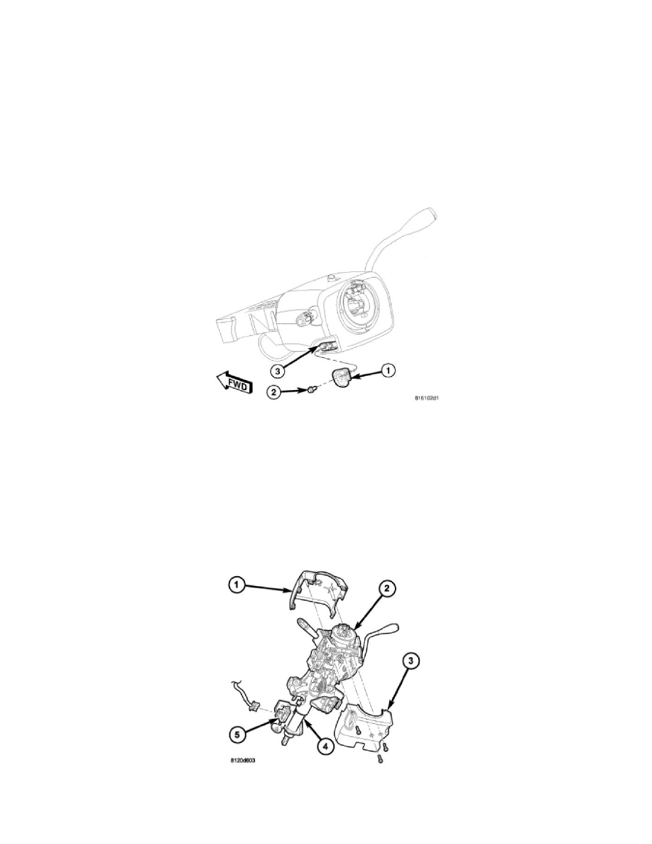
7. Remove the screw (2) that secures the tilt steering column knob (1) and remove it from the tilt actuator (3) on the left side of the column.
8. From below the steering column, remove the two outboard screws that secure the upper column shroud (1) to the lower shroud (3).
9. Using hand pressure, push gently inward on both sides of the upper shroud above the parting line of the lower shroud to release the snap features
that secure the two shroud halves to each other.