
RAM 3500 HD Truck 2WD L6-6.7L DSL Turbo (2008)
CAMBER: The wheel camber angle is preset and is not adjustable.
CASTER adjustment: Check the caster of the front axle for correct angle. Be sure the axle is not bent or twisted. Road test the vehicle and make left
and right turns. Observe the steering wheel return-to-center position. Low caster will cause poor steering wheel returnability.
For 2500/3500, caster can be adjusted by rotating the cams (3) on the lower suspension arm.
For 4500/5500, caster can be adjusted by loosening the bolts on the lower suspension arm, moving the arm within the slot and tightening the bolt.
TOE POSITION: The wheel toe position adjustment should be the final adjustment.
1. For 4500/5500 only, if an alignment is being performed without having replaced the LH tie rod end, the Tie Rod Ball Stud Housing
Misalignment Check 4500/5500 procedure must be performed prior to loosening any adjustment sleeve. If the LH tie rod end has just been
replaced, proceed with step 2.
2. Start the engine and turn wheels both ways before straightening the wheels. Center and secure the steering wheel and turn off engine.
3. Loosen the adjustment sleeve clamp bolts.
NOTE: With the vehicle in a level position, verify the drag link/tie rod ball joints are not twisted and are centered. Rotate drag link/tie rod
until ball joints are level.
4. Adjust the right wheel toe position with the drag link adjuster sleeve. Turn the sleeve until the right wheel is at the correct specification. Verify a
level drag link ball joint. Position clamp bolts to their original position and tighten to specifications. Make sure the toe setting does not change
during clamp tightening.
5. Adjust the left wheel toe position with the tie rod adjuster sleeve. Turn the sleeve until the left wheel is at the correct specification. Verify a level
tie rod ball joint. Position clamp bolts to their original position and tighten to specifications. Make sure the toe setting does not change during
clamp tightening.
CAUTION: For 4500/5500, setting the toe can put the tie rod ball stud alignment out of specifications causing damage to the LH tie rod. The
procedure must be run again to verify or reset.
6. For 4500/5500 only, perform the Tie Rod Ball Stud Housing Misalignment Check 4500/5500 to verify it is still within specifications.
NOTE: After setting toe to specifications, normalization of the tie rod to knuckle must be verified to be sure that the adjustments are correct.
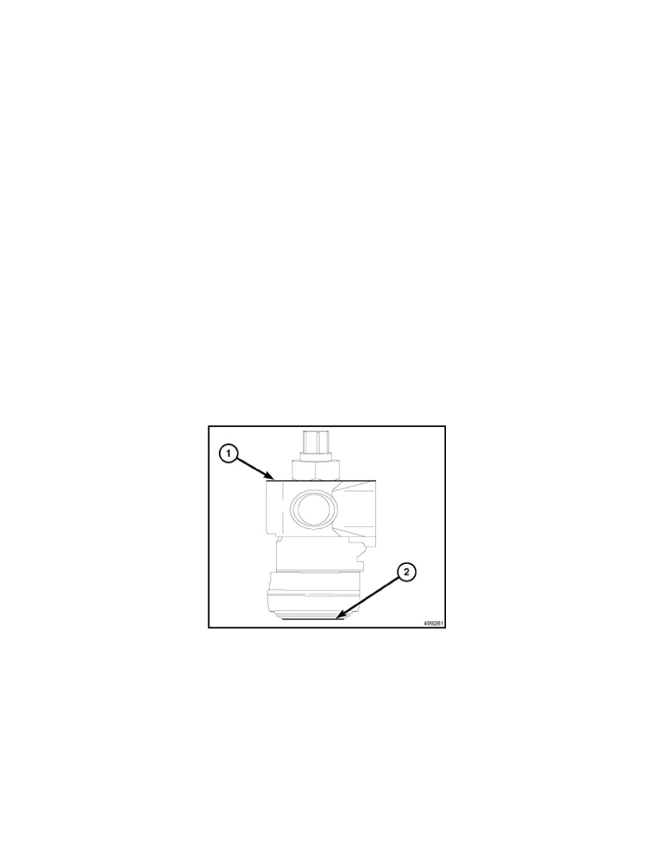
7. For 2500/3500, to normalize, venfy the lower surface of the outer tie rod socket (2) is parallel to the upper surface ofthe knuckle (1). Rotate the
drag link/tie rod until ball joint to knuckle is parallel.
NOTE: Toe setting may change during tightening, Make sure to verify reading after tightening.
8. Verify the steering wheel is straight and the toe settings are correct (repeat steps 2-6 if necessary).
9. Road test the vehicle.
Toe Adjustment - Rack and Pinion Steering System
TOE ADJUSTMENT - RACK AND PINION STEERING SYSTEM