
RAM 3500 HD Truck 2WD L6-6.7L DSL Turbo (2008)
NOTE: Extreme pressure lubrication must be used on the threaded portions of the tool. This will increase the longevity of the tool and insure
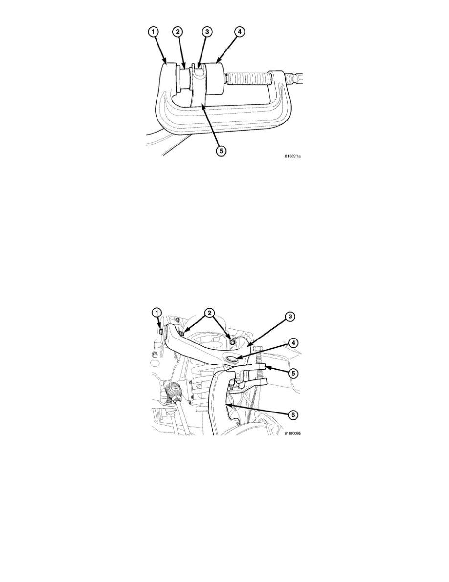
proper operation during the removal and installation process.
3. Remove the bushing (3) from the upper control arm (5) using special tool C-4212F (PRESS) (1), 9777-3 (receiver) (4), and 9777-2 (driver) (2).
Lower Control Arm Shock Bushing - IFS 4X4
LOWER CONTROL ARM SHOCK BUSHING - IFS 4X4
1. Raise and support the vehicle.
2. Remove the tire and wheel assembly.
3. Support the lower control arm outboard end.
4. Remove the caliper adapter with the caliper See: Brakes and Traction Control/Disc Brake System/Brake Caliper/Service and Repair/Removal and
Replacement/Disc Brake Caliper Adapter - Removal .
5. Remove the rotor See: Brakes and Traction Control/Disc Brake System/Brake Rotor/Disc/Service and Repair/Removal and Replacement/Brake
Rotor - Removal .
6. Remove the upper ball joint retaining nut and separate the upper ball joint (4) from the knuckle (6) using separator 9360 (5).