
RAM 3500 HD Truck 2WD L6-6.7L DSL Turbo (2008)
Front Steering Knuckle: Service and Repair
Front Steering Knuckle - Installation
(LD) 4X2 & 4X4 - Independent Front Suspension
(LD) 4X2 & 4X4
CAUTION: The ball joint stud tapers must be CLEAN and DRY before installing the knuckle. Clean the stud tapers with mineral spirits to
remove dirt and grease.
NOTE: When installing hub/bearing with ABS brakes, position the speed sensor opening towards the front of the vehicle.
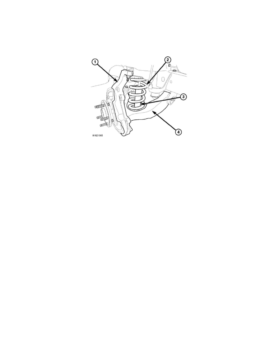
1. Install the hub/bearing to the steering knuckle (1) and tighten the bolts to 163 Nm (120 ft. lbs.).
2. Install the knuckle (1) onto the upper and lower ball joints.
3. Install the upper and lower ball joint nuts. Tighten the upper ball joint nut to 54 Nm (40 ft. lbs.) (an additional 90° turn is required) and the lower
ball joint nut to 52 Nm (38 ft. lbs.)(an additional 90° turn is required).
4. Remove the hydraulic jack from the lower suspension arm (4).
5. Install the tie rod end and tighten the nut to 61 Nm (45 ft. lbs.).
6. Install the front halfshaft into the hub/bearing (if equipped).
7. Install the the halfshaft nut and tighten to 251 Nm (185 ft. lbs.) (if equipped).
8. Install the ABS wheel speed sensor (if equipped) See: Brakes and Traction Control/Antilock Brakes / Traction Control Systems/Wheel Speed
Sensor/Service and Repair/Front Wheel Speed Sensor - Installation and brake shield, rotor and caliper See: Brakes and Traction Control/Disc
Brake System/Brake Rotor/Disc/Service and Repair/Removal and Replacement/Brake Rotor - Installation .
9. Install the wheel and tire assembly See: Wheels and Tires/Service and Repair/Removal and Replacement .
10. Remove the support and lower the vehicle.
11. Perform a wheel alignment See: Alignment/Service and Repair .
(HD) 4X2 - Independent Front Suspension
(HD) 4X2
CAUTION: The ball joint stud tapers must be CLEAN and DRY before installing the knuckle. Clean the stud tapers with mineral spirits to
remove dirt and grease.
NOTE: When installing hub/bearing with ABS brakes, position the speed sensor opening towards the front of the vehicle.
1. Install the hub/bearing to the steering knuckle and tighten the bolts to 176 Nm (130 ft. lbs.).
2. Install the knuckle onto the upper and lower ball joints.
3. Install the upper and lower ball joint nuts. Install and tighten the upper ball joint nut, to 54 Nm (40 ft. lbs.). Then Install and tighten the lower ball
joint nut to 135 Nm (100 ft. lbs.).
4. Remove the hydraulic jack from the lower suspension arm.
5. Install the tie rod end and tighten the nut to 61 Nm (45 ft. lbs.).
6. Install the ABS wheel speed sensor if equipped See: Brakes and Traction Control/Antilock Brakes / Traction Control Systems/Wheel Speed
Sensor/Service and Repair/Front Wheel Speed Sensor - Installation and brake shield, rotor and caliper See: Brakes and Traction Control/Disc
Brake System/Brake Rotor/Disc/Service and Repair/Removal and Replacement/Brake Rotor - Installation .
7. Install the wheel and tire assembly See: Wheels and Tires/Service and Repair/Removal and Replacement .
8. Remove the support and lower the vehicle.