
RAM 3500 HD Truck 4WD L6-6.7L DSL Turbo (2008)
Camshaft: Removal and Replacement
Camshaft - Removal
CAMSHAFT
1. Disconnect both battery negative cables.
2. Recover A/C refrigerant (if A/C equipped). See: Heating and Air Conditioning/Service and Repair/Refrigerant System Recovery
3. Raise vehicle on hoist.
4. Drain engine coolant into container suitable for re-use. See: Cooling System/Service and Repair
5. Lower vehicle.
6. Remove radiator upper hose.
7. Remove viscous fan/drive/shroud assembly. See: Cooling System/Radiator Cooling Fan/Service and Repair/Removal and Replacement/Radiator
Fan - Removal
8. Disconnect the coolant recovery bottle hose from the radiator filler neck.
9. Disconnect lower radiator hose from radiator outlet.
10. Automatic Transmission models: Disconnect transmission oil cooler lines from front of radiator using Special Tool 6931 (unless equipped with
finger-release disconnect).
11. Remove radiator mounting screws and lift radiator out of engine compartment.
12. Remove upper radiator support panel.
13. If A/C equipped, disconnect A/C condenser refrigerant lines.
14. Disconnect charge air cooler piping from the cooler inlet and outlet.
15. Remove the two charge air cooler mounting bolts.
16. Remove charge air cooler (and A/C condenser if equipped) from vehicle.
17. Remove accessory drive belt. See: Drive Belts, Mounts, Brackets and Accessories/Drive Belt/Service and Repair/Removal and
Replacement/Accessory Drive Belt - Removal
18. Remove accessory drive belt tensioner.
19. Remove the fan support/hub assembly.
20. Remove crankshaft damper. See: Cylinder Block Assembly/Harmonic Balancer - Crankshaft Pulley/Service and Repair/Removal and
Replacement/Vibration Damper - Removal
21. Remove the gear cover-to-housing bolts and gently pry the cover away from the housing, taking care not to mar the sealing surfaces. Remove dust
seal with cover.
22. Using Special Tool 7471-B Crankshaft Barring Tool, rotate the crankshaft to align the timing marks on the crankshaft and the camshaft gears.
23. Remove the cylinder head cover. See: Cylinder Head Assembly/Valve Cover/Service and Repair/Removal and Replacement/Cylinder Head Cover
- Removal
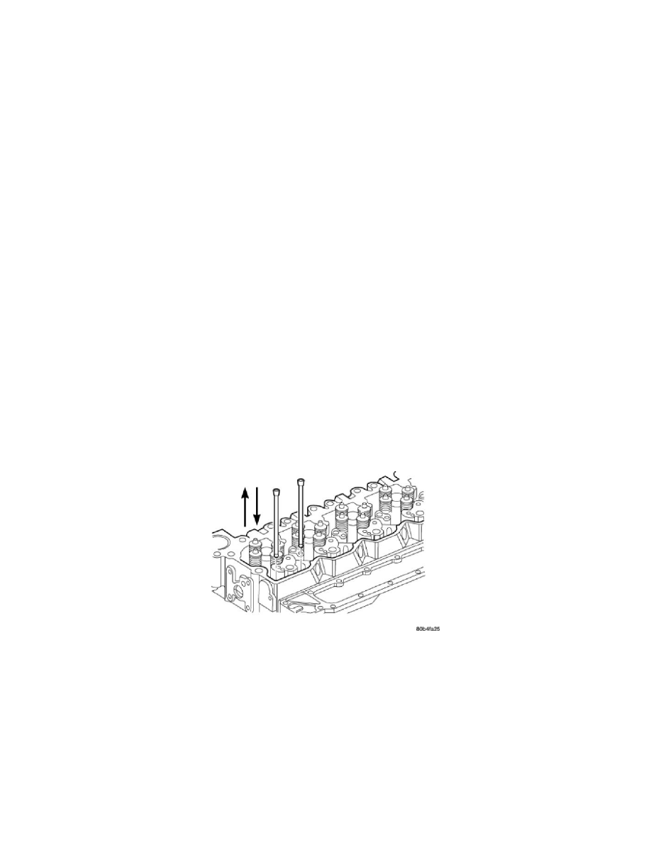
24. Remove the rocker arms, cross heads, and push rods. Mark each component so they can be installed in their original positions.
NOTE: The # 5 cylinder intake and the # 6 cylinder intake and exhaust pushrods are removed by lifting them up and through the
provided cowl panel access holes. Remove the rubber plugs to expose these relief holes.