
RAM 3500 Van V8-360 5.9L Magnum (1995)
EGR Control Solenoid: Component Tests and General Diagnostics
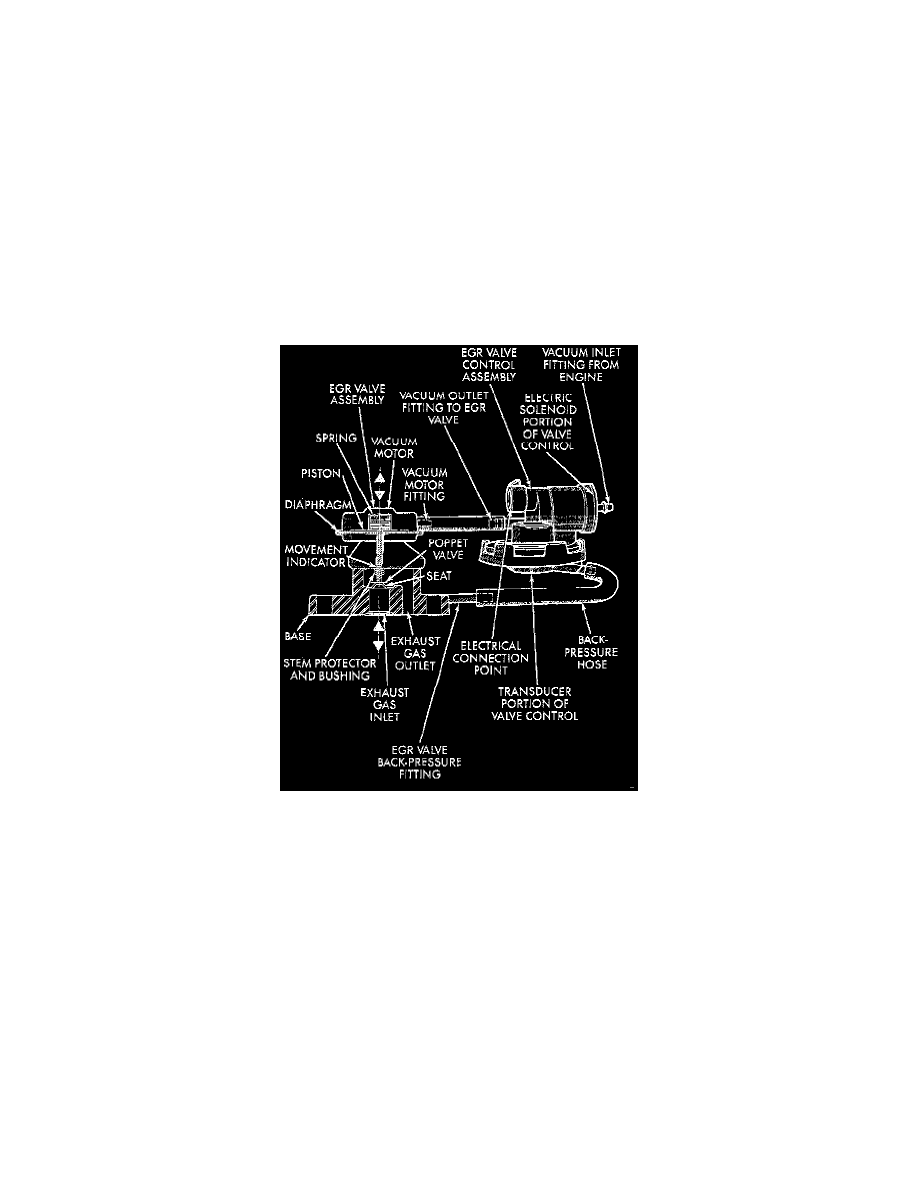
TESTING ELECTRICAL SOLENOID PORTION OF VALVE CONTROL
This is not to be used as a complete test of the EGR system.
Electrical operation of the valve control should be checked with the DRB scan tool. Replace the solenoid if necessary.
TESTING VACUUM TRANSDUCER PORTION OF VALVE CONTROL
The first part of this test will determine if the transducer diaphragm at the back-pressure side of the valve control has ruptured or is leaking. The
second part of this test will determine if engine vacuum (full manifold) is flowing from the inlet side to the outlet side of the valve control. This is
not to be used as a complete test of the EGR system.
1. Electrical operation of the valve control should first be checked with the DRB scan tool before proceeding with the vacuum test.
2. Disconnect the rubber back-pressure hose from the fitting on the bottom of the EGR valve control.
3. Connect a hand-held vacuum pump to this fitting.
4. Apply 10 inches of vacuum to this fitting.
5. If vacuum falls off, the valve control diaphragm is leaking.
6. Replace the EGR valve control. Proceed to the next step for further testing.
EGR Valve And EGR Control Valve
7. Remove the rubber hose at the vacuum inlet fitting on the EGR valve control.
8. Connect a vacuum gauge to this disconnected hose.
9. Start the engine and bring it to operating temperature. Hold engine speed at approximately 1500 RPM.
10. Check for steady engine vacuum (full manifold) at this hose.
11. If full engine vacuum is not present, check vacuum line to engine and repair as necessary before proceeding to the next step.
12. Reconnect the rubber hose to the vacuum inlet fitting on the EGR valve control.
13. Disconnect the rubber hose at the vacuum outlet fitting on the EGR valve control.
14. Connect a vacuum gauge to this fitting.
15. Disconnect the electrical connector at the valve control. This will simulate an open circuit (no ground from PCM) at the valve control.
16. Start the engine and bring to operating temperature. Hold the engine speed at approximately 2000 RPM while checking for full engine vacuum at
fitting. To allow full vacuum flow through the valve control, exhaust backpressure must be present at valve control. It must be high enough to hold
the bleed valve in the transducer portion of the valve control closed. Have a helper momentarily (a second or two) hold a rag over the tailpipe
opening to build some exhaust backpressure while observing the vacuum gauge. Heavy gloves should be worn. DO not cover the tailpipe opening
for an extended period of time as damage to components or overheating may result.
As temporary back-pressure is built, full manifold vacuum should be observed at the vacuum control outlet fitting. Without backpressure and the
engine at approximately 2000 RPM, the gauge reading will be low. This low reading is normal. At idle speed, the gauge reading will be erratic.
This is also normal.