
Testing and Inspection - Blower Motor Relay for RAM 3500 Van V8-59L VIN Z LDC (1998)
Blower Motor Relay: Testing and Inspection
Blower Motor Relay
Blower Motor Relay
Relay Test
The blower motor relays used for the front heater-only or heater-A/C systems and for the optional rear heater-A/C unit can be tested in the same manner.
The front blower motor relay is located in the Power Distribution Center (PDC). The rear blower motor relay is located in a connector that is attached to
the back of the rear heater-A/C unit. See Blower Motor Relay in the Removal and Installation for the procedures to remove the relay, to perform the
following tests:
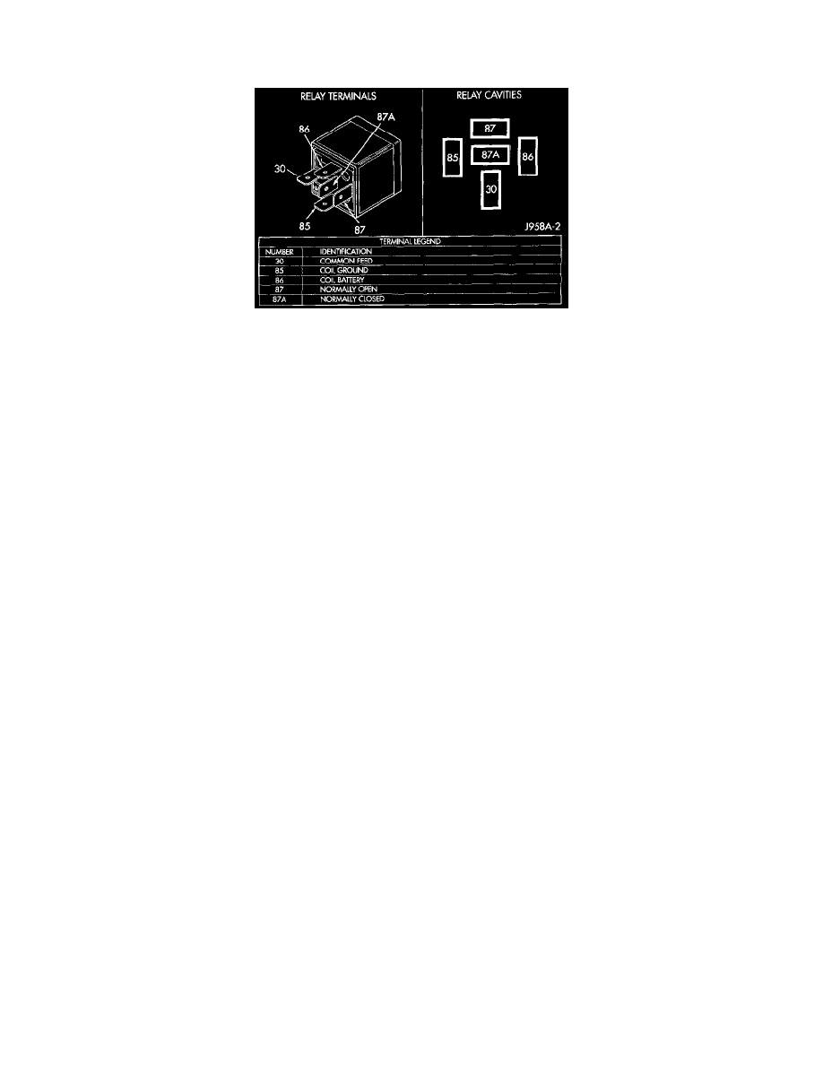
1. A relay in the de-energized position should have continuity between terminals 87A and 30, and no continuity between terminals 87 and 30. If OK,
go to Step 3. If not OK, replace the faulty relay
2. Resistance between terminals 85 and 86 (electromagnet) should be 75 ± 5 ohms. If OK, go to Step 4. If not OK, replace the faulty relay.
3. Connect a battery to terminals 85 and 86. There should now be continuity between terminals 30 and 87, and no continuity between terminals 87A
and 30. If OK, see Relay Circuit Test in the Diagnosis and Testing. If not OK, replace the faulty relay.
Relay Circuit Test
1. The relay common feed terminal cavity (30) is connected to fused battery feed directly from a fuse in the Power Distribution Center (PDC), and
should be hot at all times. Check for battery voltage at the PDC cavity for relay terminal 30. If OK, go to Step 3. If not OK repair the open circuit
to the PDC fuse as required.
2. The relay normally closed terminal cavity (87A) is not used for this application. Go to Step 4.
3. The relay normally open terminal cavity (87) is connected to the blower motor. When the relay is energized, terminal 87 is connected to terminal
30 and provides full battery current to the blower motor feed circuit. There should be continuity between the PDC cavity for terminal 87 and the
blower motor relay output circuit cavity of the blower motor wire harness connector at all times. If OK, go to Step 5. If not OK, repair the open
circuit to the blower motor as required.
4. The coil battery terminal cavity (86) is connected to the ignition switch. When the ignition switch is placed in the On position, fused ignition
switch output is directed from a fuse in the junction block to the relay electromagnetic coil to energize the relay. There should be battery voltage at
the PDC cavity for relay terminal 86 with the ignition switch in the On position. If OK, go to Step 6. If not OK, repair the open circuit to the
junction block fuse as required.
5. The coil ground terminal cavity (85) is connected to ground. This terminal supplies the ground for the relay electromagnetic coil. There should be
continuity between the PDC cavity for relay terminal 85 and a good ground at all times. If not OK, repair the open circuit as required.