
RAM 3500 Van V8-5.9L VIN Z LDC (1998)
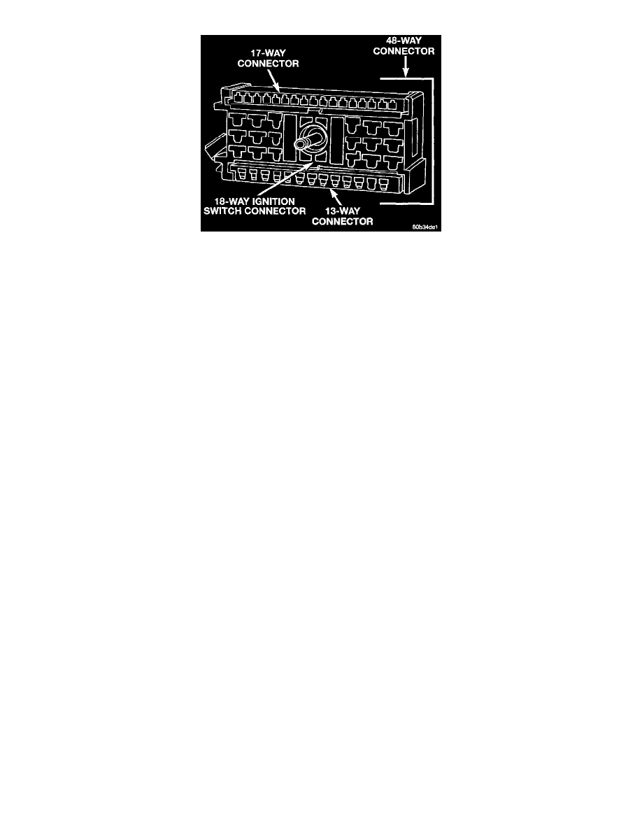
Steering Column 48-Way Connector (Male C0nnector To Column Shown)
i.
Separate 13-way multi-function switch connector from 18-way ignition switch connector.
j.
Separate multi-function switch wire harnesses from ignition switch wiring harness.
k. Remove wiring harness and ignition switch as an assembly from steering column.
INSTALLATION
1. KEY LOCK CYLINDER INSTALLATION:
a. Place key into lock cylinder.
b. Place key lock cylinder into steering column by aligning positioning tab on lock cylinder to positioning slot on steering column. Locking tab
should also be aligned to locking tab slot.
c. Press on lock cylinder until retaining pin engages.
d. Rotate key to OFF position.
e. Check for proper retention of lock cylinder by attempting to pull out on lock cylinder.
2. IGNITION SWITCH INSTALLATION:
a. Position switch and wire harness assembly to steering column.
b. Install switch screws and tighten to 1.4 N.m (12 in. lbs.) torque.
c. Carefully route ignition switch wire harness down to bottom of steering column.
d. If equipped with overdrive (OD) transmission, clip OD wire harness to ignition switch.
e. Route alarm switch wire harness around ignition switch.
f.
Attach alarm switch to steering column by rotating and snapping into position).
g. Attach 13-way multi-function switch connector to ignition switch 18-way connector.
h. Attach 17-way multi-function switch connector to ignition switch 18-way connector.
i.
Attach both 48-way electrical connectors together (1 bolt). Tighten bolt to 7 N.m (62 in. lbs.) torque.
j.
Install new tie wraps in their previously noted positions.
k. If equipped with a tilt steering wheel, operate tilt mechanism while observing wiring harnesses for binding. Correct binding if necessary.
l.
Operate shift lever while observing wiring harnesses for binding. Correct binding if necessary.
3. A 2-5/8" long plastic spacer is attached to inside of upper shroud. Before positioning shroud to column, verify spacer is tightened to upper shroud.
4. Position upper shroud to steering column.
5. Install 2 upper shroud screws.
6. Position rubber shields for shift lever and multi-function switch into upper shroud.
7. Position lower shroud hooks into pins on upper shroud.
8. Snap lower shroud to upper shroud.
9. Install 2 lower shroud screws.
10. Install tilt-wheel lever (snaps in).
11. Shifter should lock in PARK position when key is in LOCK position. Shifter should unlock when key rotated to ON position.
12. Check for proper operation of ignition switch in ACCESSORY, LOCK, OFF, ON, RUN, and START positions.
13. Steering wheel should lock when key is in LOCK position. Rotate steering wheel to verify Steering wheel should unlock when key is rotated to ON
position.
14. Connect negative battery cable to battery.