
RAM 50 4WD L4-143 Manual Steering Gear Service - Page 920
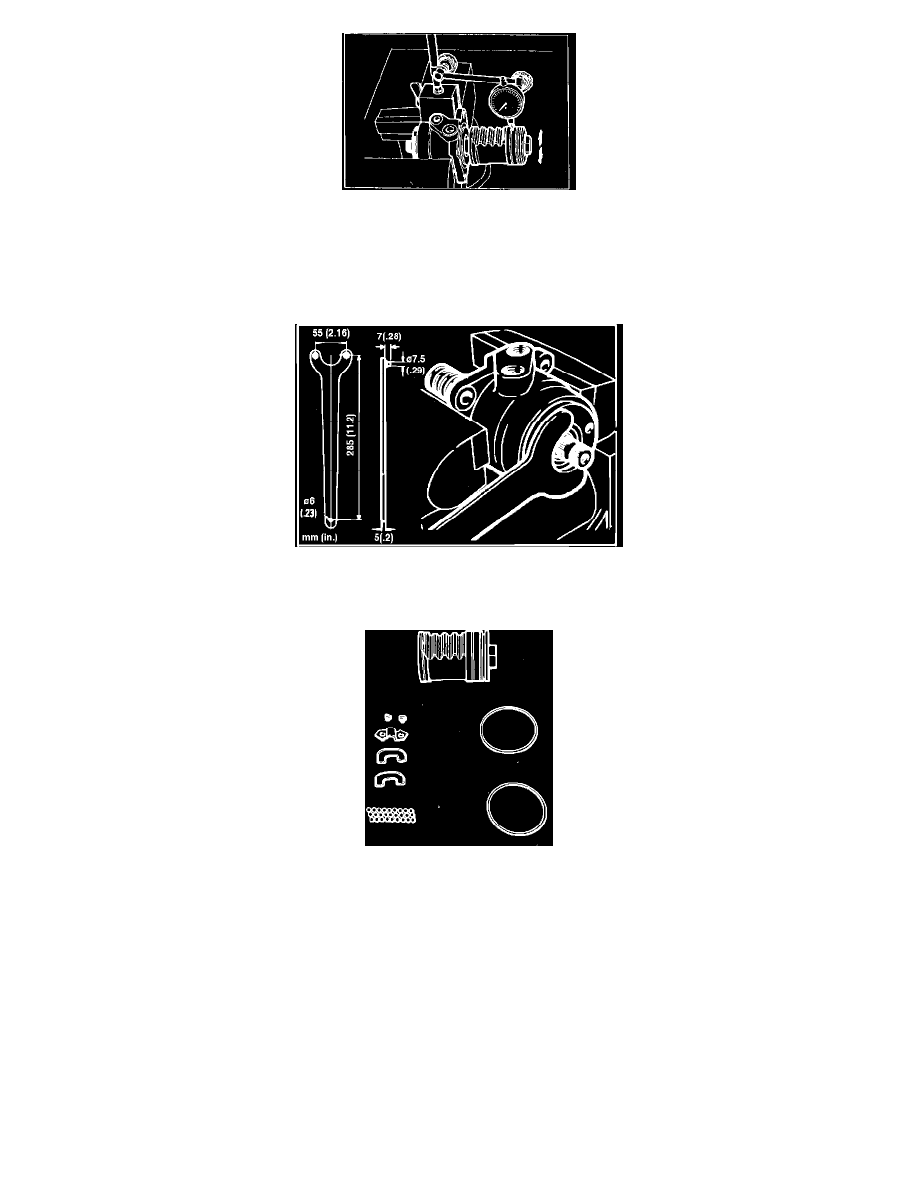
Fig. 5 Measurement of rack piston backlash
4. Secure valve housing in vise with dial indicator as shown, then move rack and piston up and down to check backlash between groove of rack
piston and the balls. Backlash should be 0.0039 inch for large gear and 0.080 inch for small gear maximum. Measure backlash with piston fully
tightened and loosened 2 turns. If backlash exceeds limit, replace ball screw unit and rack piston as an assembly.
5. Remove rack piston from valve housing by turning counterclockwise. Do not lose any of the 26 balls.
Fig. 6 Removal of top cover
6. Remove top cover of valve housing using tool No. MB990853 for small gear or special spanner wrench as shown.
Fig. 7 Components of rack piston
7. Remove circulator holder, circulator, seal ring and O-ring from rack piston.
8. Remove thrust unit, thrust needle roller bearing, seal rings and O-rings from input worm unit.
9. To disassemble subassembly components, proceed as follows:
a. Turn in adjusting bolt at tip of cross shaft and remove side cover. Do not lose any needle bearing rollers.
b. Remove adjusting bolt and plate, O-ring and needle bearing from side cover. Do not remove O-ring and sealing at rear of needle bearing if no
oil leaks from thread of adjusting bolt. Also, do not remove bleeder plug unless necessary.
c. Remove seal ring and O-ring from valve housing.
d. Remove ball bearing and oil seal from top cover.
e. Remove snap ring at bottom of gearbox, then back-up ring and oil seal. Pull out seal housing.
f.
Remove seal ring and O-rings from seal housing.
10. To assemble subassembly components, proceed as follows. Replace O-rings, seal rings and oil seals whenever disassembled.
a. Apply thin coat of multi-purpose grease to bearing surface of needle bearing and install rollers into side cover, then apply grease to bottom of
side cover.
b. Insert adjusting bolt and plate into "T" slot on top of cross shaft, and adjust play to 0-.002 inch by selecting proper adjusting plate. When
installing adjusting plate, place chamfered portion of plate to contact surface of cross shaft.