
RAM 5500 Chassis Cab Truck 2WD L6-6.7L DSL Turbo (2008)
11. Compress the valve springs at cylinders. # 1 and # 6 as follows:
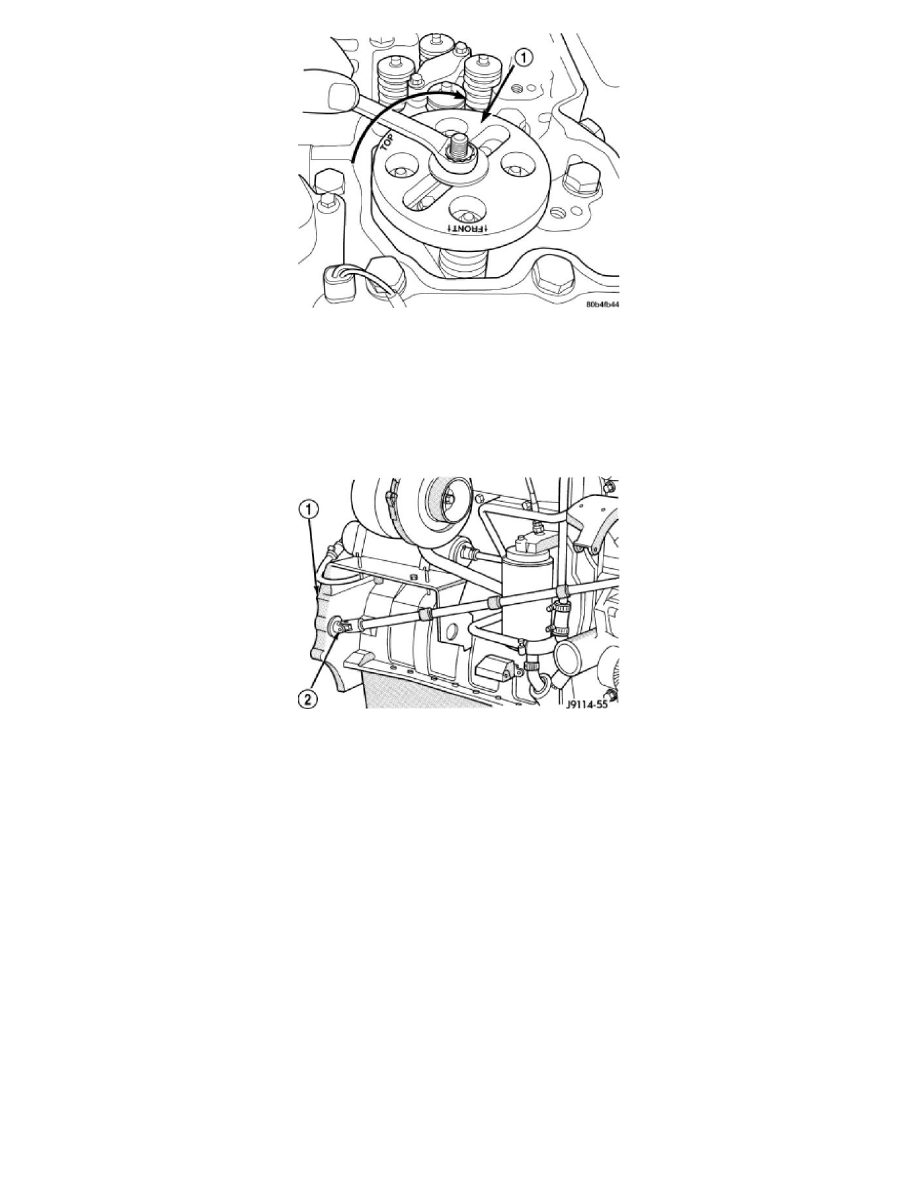
a. Install the valve spring compressor mounting base as shown in.
b. Install the top plate, washer, and nut. Using a suitable wrench tighten the nut (clockwise) to compress the valve springs and remove the collets.
c. Rotate the compressor nut counterclockwise to relieve tension on springs. Remove spring compressor.
d. Remove and replace retainers, springs, and seals as necessary.
e. Do not rotate the engine until the springs and retainers are reinstalled.
f.
Install seals, springs and retainers. Install spring compressor, compress valve springs and install the collets.
g. Release the spring tension and remove the compressor. Verify that the collets are seated by tapping on the valve stem with a plastic hammer.
12. Using the crankshaft barring tool (2), rotate the engine until the next crankshaft damper paint mark aligns with the mark you placed on the cover.
In this position, cylinders # 2 and # 5 can be serviced.
13. Repeat the valve spring compressing procedure previously performed and service the retainers, springs, and seals as necessary.
14. Using the crankshaft barring tool, rotate the engine until the next crankshaft damper paint mark aligns with the mark you placed on the cover. In
this position, cylinders # 3 and # 4 can be serviced.
15. Repeat the spring compressing procedure previously performed and service the retainers, springs, and seals as necessary.
Installation
INSTALLATION
1. Install rocker housing. See: Valve Cover/Service and Repair/Removal and Replacement/Cylinder Head Cover - Installation
2. Install fuel injectors and high pressure fuel lines.
3. Lubricate the valve tips and install the crossheads in their original locations.
4. Lubricate the crossheads and push rod sockets and install the rocker arms and pedestals in their original locations. Tighten bolts to 36 Nm (27 ft.
lbs.) torque.
5. Verify valve lash adjustment See: Procedures .
6. Install cylinder head cover gasket onto rocker housing. See: Valve Cover/Service and Repair/Removal and Replacement/Cylinder Head Cover -
Installation
7. Install injector solenoid nuts.
8. Connect injector harness connectors.
9. Install cylinder head cover. See: Valve Cover/Service and Repair/Removal and Replacement/Cylinder Head Cover - Installation
10. Connect battery negative cables.