
RAM 5500 Chassis Cab Truck 2WD L6-6.7L DSL Turbo (2008)
4. Mount the Inclinometer - 10326-2 (2) on the flat bottom surface of Tie Rod Alignment Adapter - 10326-1 (1) in the fore-aft orientation. Record
the tie rod angle, then repeat steps 3, 4 on the LH tie rod end.
5. Determine the offset of the RH and LH tie rod ball stud housings by calculating the difference between the LH and RH ball stud angles. For
example, if one side is +3 degrees and the other side is -4 degrees then the difference is 7 degrees.
-
Equal to or less than 3 degree difference - no further action needs to be taken, return to the previous procedure step and continue that
procedure.
-
Over 3 degree difference with a new LH tie rod end - Loosen the LH tie rod adjustment sleeve bolts and rotate the tie rod end to adjust the ball
stud housing to within 3 degrees of the RH side, then proceed with alignment or toe adjustment.
-
Over 3 degree difference without a new LH tie rod end - Replace the LH tie rod end.
NOTE: Any future alignment process on a 4500/5500 should use this procedure.
Curb Height Measurement (LD)
CURB HEIGHT MEASUREMENT (LD)
The wheel alignment is to be checked and all alignment adjustments made with the vehicle at its required curb height specification.
Vehicle height is to be checked with the vehicle on a flat, level surface, preferably a vehicle alignment rack. The tires are to be inflated to the
recommended pressure. All tires are to be the same size as standard equipment. Vehicle height is checked with the fuel tank full of fuel, and no passenger
or luggage compartment load.
Inspect the vehicle for bent or weak suspension components. Compare the parts tag on the suspect coil spring(s) to the parts book and the vehicle sales
code, checking for a match. Once removed from the vehicle, compare the coil spring height to a correct new or known good coil spring. The heights
should vary if the suspect spring is weak.
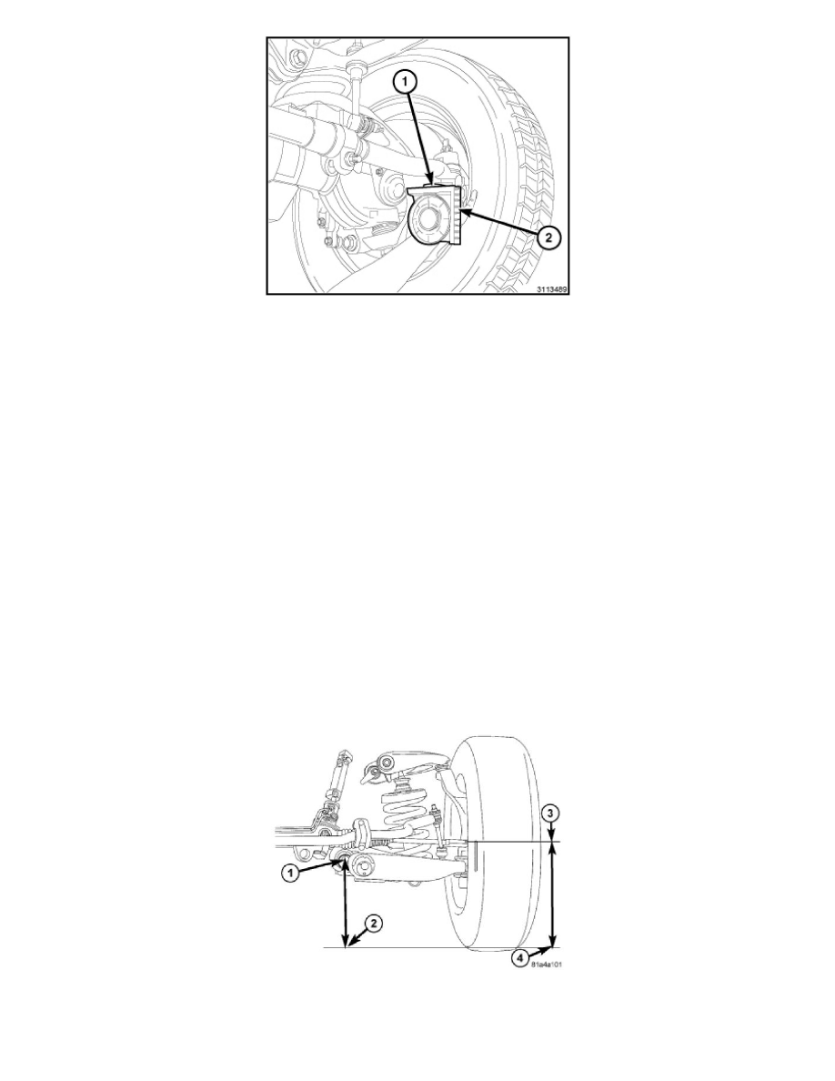
1. Front - On each side of the vehicle, measure the distance from the center of the rear lower control arm bolt (1) to the ground (2) Record the
measurement. Next measure the distance from the spindle center (3) to the ground (4) Record the measurement.
2. Take the two measurements and subtract them to get the curb height specification.