
RAM 5500 Chassis Cab Truck 2WD L6-6.7L DSL Turbo (2008)
Ball Joint: Service and Repair
Front Upper Ball Joint - Installation
Independent Front Suspension
INSTALLATION
NOTE: Extreme pressure lubrication must be used on the threaded portions of the tool. This will increase the longevity of the tool and insure
proper operation during the removal and installation process.
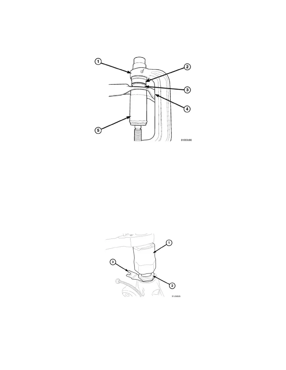
1. Install the ball joint (3) into the upper control arm (4) and press in using special tools C-4212-F (press) (1), 9652 (Driver) (2) and 8445-1
(Receiver) (5).
2. Install the upper ball joint into the knuckle.
3. Install the upper ball joint retaining nut and tighten to 54 Nm (40 ft. lbs.)(on 1500 series only an additional 90° turn is required) or 68 Nm (50 ft.
lbs.)(HD).
4. Install the wheel speed sensor wire to the knuckle (HD) and to the upper control arm (LD).
5. Install the tire and wheel.
6. Remove the supports and lower the vehicle.
7. Perform a wheel alignment See: Alignment/Service and Repair .
4500 & 5500 - Link/Coil
4500 & 5500
1. Install the wheel speed sensor bracket (3) to the upper ball joint (2).
2. Screw the upper ball joint (2) into the steering knuckle. Tighten to 400 Nm (295 ft.lbs.).
3. Reconnect the wheel speed sensor wire into the bracket (3).