
RAM 5500 Chassis Cab Truck 4WD L6-6.7L DSL Turbo (2011)
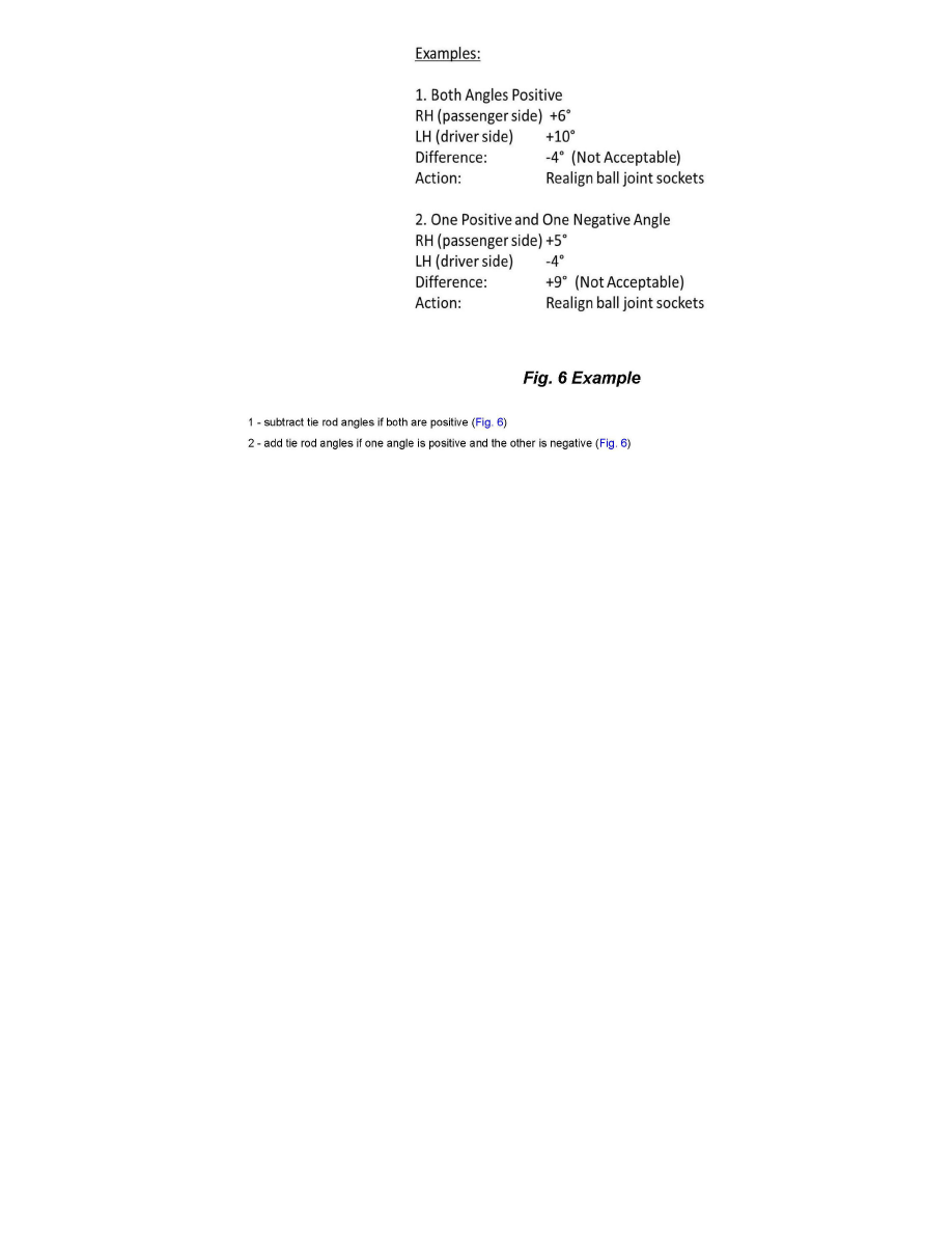
6. Calculate the amount of misalignment between the right and left tie rod ball stud housings by adding or subtracting the left and right measurement as
follows:
NOTE:
The right side is only positive.
7. If the combined ball stud housing misalignment value is +/-3 degrees or less, no further action needs to be taken. If the misalignment value calculated
in Step # 6, is greater than +/-3 degrees, proceed to Step # 8.
8. Loosen the left tie rod adjuster clamp nut (Fig. 7 ) and realign the left ball stud housing by rotating the left outer tie rod until the ball stud housings
are aligned. When complete, tie rod alignment measurement must be +/- 3° or less.
9. Tighten the adjuster clamp nut to 40 ft-lb (+/-10 ft-lb) confirm ball stud housing alignment is +/- 3 degrees or less. Verify toe-in is within tolerance.
NOTE:
ANY FUTURE ALIGNMENT PROCEDURES OR SUSPENSION COMPONENT REPLACEMENTS MUST USE THIS BALL SOCKET
ALIGNMENT PROCEDURE WITH THE INCLINOMETER TO ASSURE BALL STUD SOCKET ALIGNMENT.
POLICY:
Information Only: This procedure will be paid through standard tie rod installation and alignment procedures.
Disclaimer:
This bulletin is supplied as technical information only and is not an authorization for repair.