
Ram Raider L4-2555cc 2.6L SOHC (1987)
Connecting Rod: Service and Repair
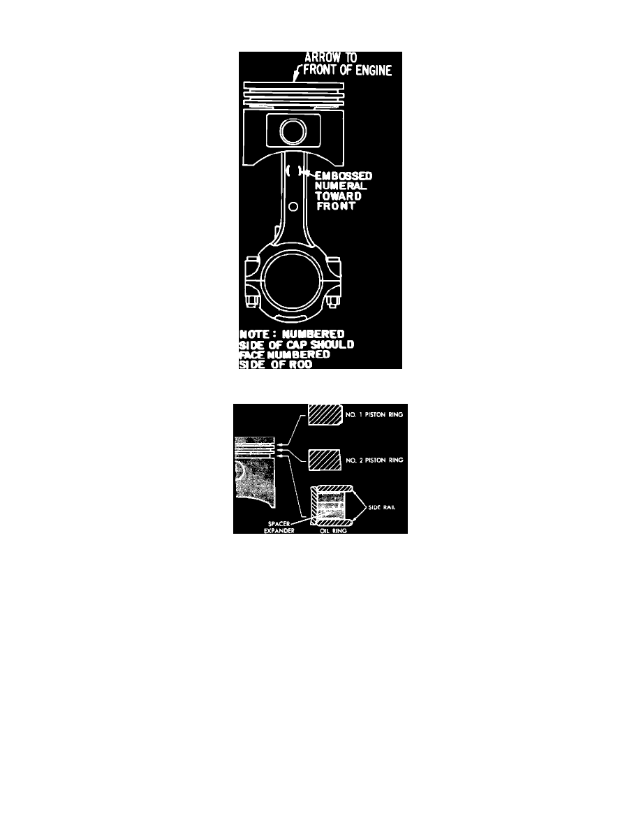
Fig. 26 Piston & rod assembly
Fig. 27 Piston ring installation
During installation of piston and rod assembly, arrow at top of piston must face toward front of engine (timing chain), Fig. 26. Refer to Fig. 27 for
correct piston ring installation.
1.
Note the following ring groove clearances:
a.
No. 1 upper: 0.0024 - 0.0039 inch (0.06 - 0. 10 mm); wear limit, .004 inch (.1 mm).
b.
No. 2 intermediate: 0.0008 - 0.0024 inch (0.02 - 0.06 mm); wear limit, .004 inch (.1 mm).
c.
Oil ring: oil ring side rails must be free to rotate after assembly.
2.
Note the following end gap clearances:
a.
No. 1 upper: 0.010 - 0.018 inch (0.25 - 0.45 mm); wear limit, .039 inch (.1 mm).
b.
No. 2 intermediate: 0.010 - 0.018 inch (0.25 - 0.45 mm); wear limit, .039 inch (.1 mm).
c.
Oil ring side rail: 0.008 - 0.035 inch (0.2 - 0.4 mm); wear limit .059 inch (1.5 mm).
3.
Connecting rod side clearance should be 0.004 - 0.010 inch (0.1 - 0.25 mm).