
Ram Raider V6-2972cc 3.0L SOHC (1989)
Crankshaft Position Sensor: Description and Operation
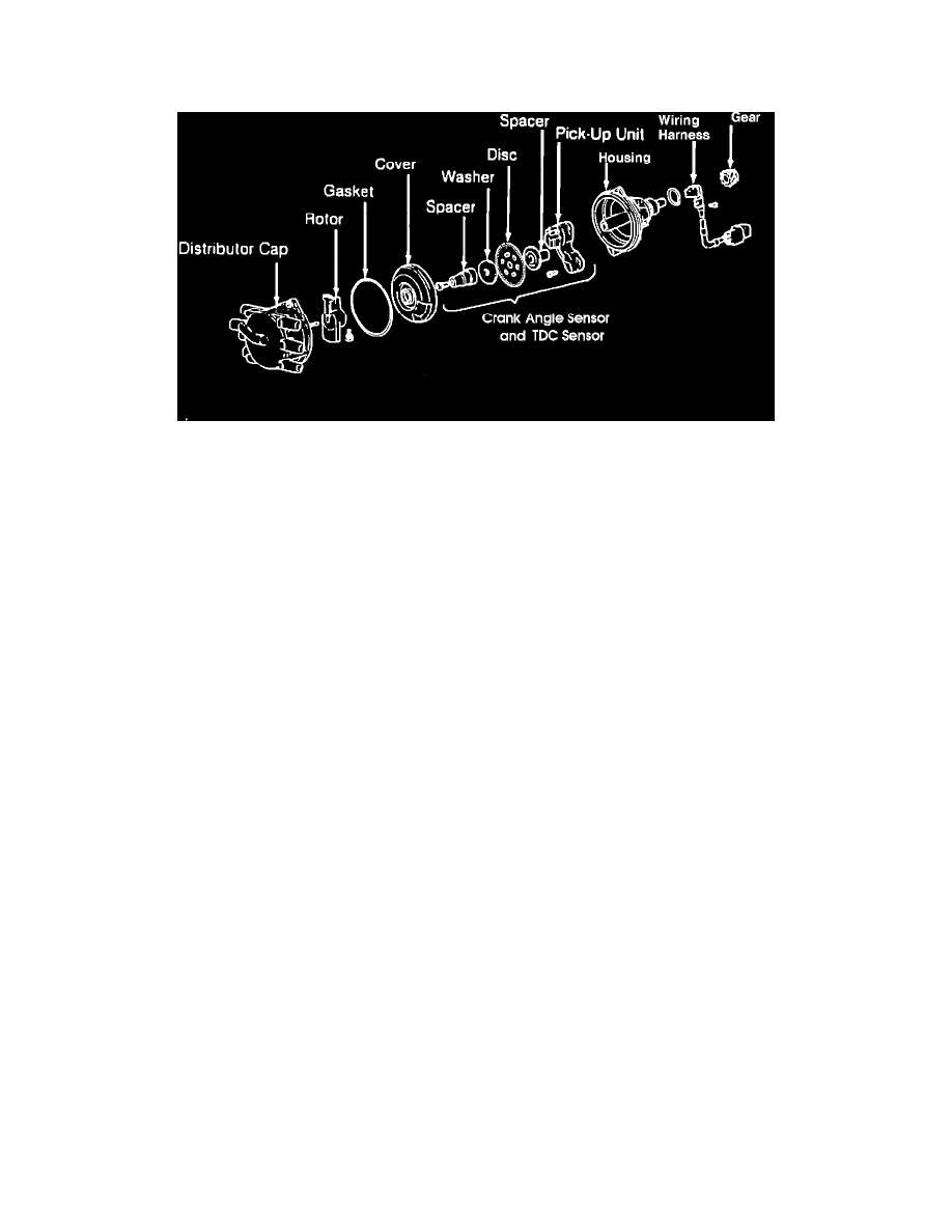
The Crank Angle Sensor and the Top Dead Center Sensor are located within the distributor housing. These sensors are incorporated into one unit, being
a disc and a pick-up unit. The disc is affixed to the distributor shaft and the light-transmitting unit is mounted stationary to the distributor housing.
Exploded View Of Distributor
The disc contains 360 slits around its circumference to indicate the crankshaft angle. An additional slit located inward from the edge is used to indicate
number one cylinder's top dead center position. The pick-up unit assembly uses two luminous diodes and two photo diodes, in order to be able to detect
the two types of slits. There is a very slight clearance between the luminous diodes and the photo diodes, and the disc rotates within this space. As the
distributor shaft rotates the slits at the discs edge pass between the light and the optical reading part of the unit. The light emitted from the luminous
diodes pass through the slits to the photo sensing diodes. When the photo diodes receive the light, they become conductive and generate a signal, which
is sent to the Control Unit.
The Control Unit is able to detect number one cylinder TDC by the signal generated through the single inner slit on the disc.
The slits at the outer circumference of the disc serve to detect the position of the crankshaft (and, therefore, the piston) relative to top dead center.
Based on these signals, the Control Unit is able to determine the fuel injection pulse width, ignition timing, and also the intake-air flow rate for each
revolution of the engine.