
Ramcharger 4WD V8-318 5.2L VIN R 4-bbl (1982)
7. Carefully remove plastic cover from lock plate, then depress lock plate and pry retaining ring out of groove with a screwdriver. Tool C-4156 can
be used to depress lock plate, however, it will make removal of retaining ring more difficult, since the full load of the retaining plate will not be
applied, allowing the retaining ring to turn.
8. Remove lock plate, cancelling cam and upper bearing spring.
9. Remove the three turn signal switch retaining screws, then place shift bowl in Low position. Wrap tape around connector wires to prevent
snagging of wires, then remove switch and wiring.
10. Insert a small screwdriver into slot next to switch mounting screw boss (right hand slot) and depress spring latch at bottom of slot to release lock,
then remove lock. The lock cylinder may be removed in any position from Accessory to On. However, the Lock position is recommended
because of its positive location.
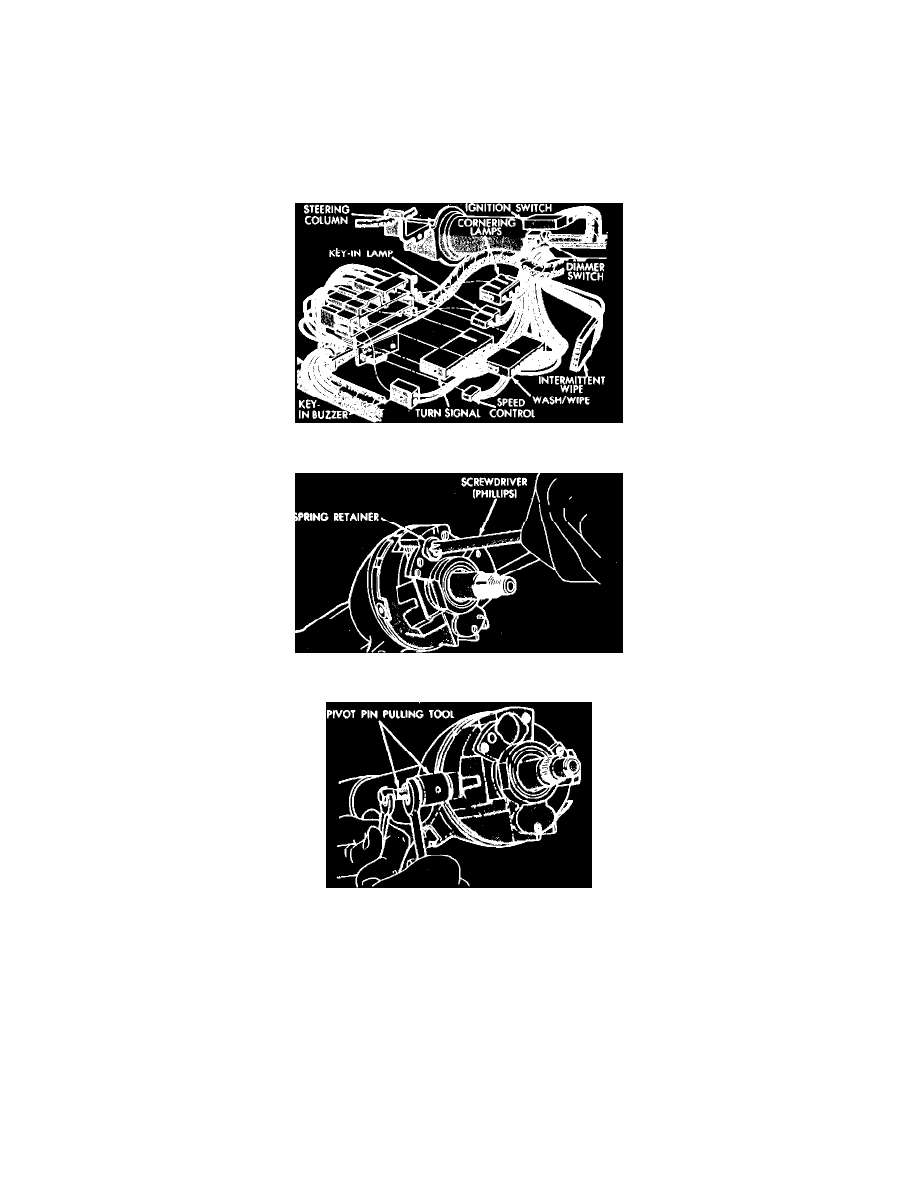
Fig. 21 Steering column electrical connectors. Front wheel drive Mini-Vans/Wagons
Fig. 22 Tilt spring retainer removal
Fig. 23 Pivot pin removal
11. If used, remove buzzer and combination switch, by pulling it straight out using a piece of stiff wire with a hook bent at one end. Insert wire in
exposed loop at wedge spring, then pull straight out. If lock cylinder has not been removed yet, place it in the On position.
12. Remove the three housing cover screws and housing cover.
13. Install tilt release lever and place column in full up position, then remove tilt spring retainer using a suitable screwdriver. Insert screwdriver in
opening, press in about 3/16 inch and turn 1/8 inch turn until ears align with grooves in housing and remove spring and guide.
14. Push upper steering shaft to allow removal of steering shaft inner race and seat.
15. With ignition switch in Accessory position, remove ignition switch mounting screws and switch.
16. Place pivot pin remover C-4016 or equivalent over pivot pin and thread small portion of screw firmly into pin. While holding screw from turning,
turn nut clockwise to remove pin from support. Remove opposite pin in same manner.
17. Using tilt release lever, disengage lock shoes, then remove bearing housing assembly by pulling upward to extend rack fully. Move housing
assembly to the left to disengage rack from actuator and remove activator assembly.
18. Remove coupling from lower end of steering shaft by removing retaining pin.