
Rampage L4-135 2.2L (1983)
Ball Stud: Service and Repair
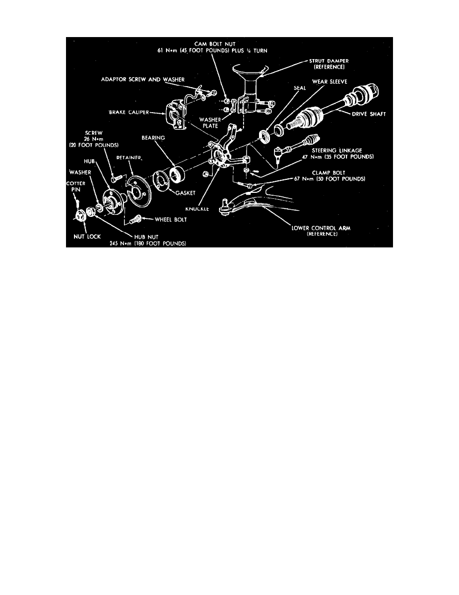
Fig. 10 Steering knuckle assembly
REMOVAL
1. Remove cotter pin and locknut.
2. Loosen hub nut with brakes applied. The hub and driveshaft are splined together through the knuckle (bearing) and retained by the hub
nut.
3. Raise and support vehicle, then remove front wheel.
4. Remove hub nut. Ensure that the splined driveshaft is free to separate from spline in hub during knuckle removal. A pulling force on the shaft can
separate the inner C/V joint. Tap lightly with a brass drift, if required.
5. Disconnect the tie rod end from steering arm with a suitable puller.
6. Disconnect brake hose retainer from strut damper.
7. Remove clamp bolt securing ball joint stud into steering knuckle and brake caliper adapter screw and washer assemblies.
8. Support caliper with a piece of wire. Do not hang by brake hose.
9. Remove rotor.
10. Mark position of camber cam upper adjusting bolt and loosen both bolts.
11. Support steering knuckle and remove cam adjusting and through bolts. Move upper knuckle "neck" from strut damper bracket and lift knuckle
from ball joint stud. Support driveshaft during knuckle removal. Do not permit driveshaft to hang after separating steering knuckle from
vehicle.
INSTALLATION
1. Place steering knuckle on lower ball joint stud and the driveshaft through hub.
2. Position upper "neck" of knuckle into strut damper bracket and install cam and through bolts. Place cam in original position. Place a 4-inch or
larger, C-clamp on strut and steering knuckle, then tighten clamp just enough to eliminate looseness between knuckle and strut. Check to ensure
that cam alignment marks made during removal are aligned, then tighten bolts to 45 ft. lbs. plus an additional 1/4 turn beyond specified torque.
Remove C-clamp.
3. Install and torque ball joint to steering knuckle clamp bolt to 50 ft. lbs. (68 Nm).
4. Install tie rod end into steering arm and torque nut to 35 ft. lbs. (47 Nm). Install cotter pin.
5. Install rotor.
6. Install caliper over rotor and position adapter to steering knuckle. Install adapter to knuckle bolts and torque to 85 ft. lbs. (115 Nm). For 1982
vehicles, or 160 ft. lbs. (216 Nm) for 1983 - 84 vehicles.
7. Attach brake hose retainer to strut damper and torque screw to 10 ft. lbs. (13 Nm).
a. Install washer and hub nut.
b. With brakes applied, torque hub nut to 180 ft. lbs. (245 Nm).
c. Install locknut and new cotter pin.