
Shadow L4-153 2.5L SOHC VIN B (1993)
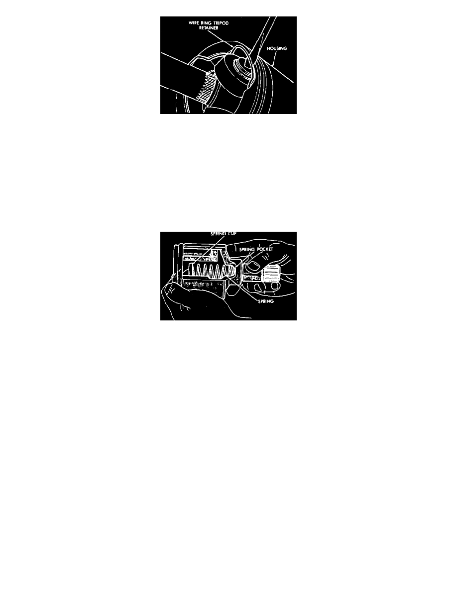
Fig. 12 Tripod From Housing Removal. S.S.G. Inner C/V Joint
5. On SSG. units, use a flathead screwdriver to pry wire ring out of groove and slide tripod from housing.
CAUTION: When removing housing from tripod, hold rollers in place on the trunnion studs to prevent rollers and needle bearings from falling
out. After tripod is out of housing, secure rollers in place with tape.
6. Remove snap ring from end of shaft, then the tripod using a brass drift.
INSPECTION
Remove grease from assembly and inspect bearing race and tripod components for wear and damage and replace as necessary. On spring loaded
joints inspect spring, spring cup and spherical end of connecting shaft for wear and damage and replace as necessary.
NOTE: Components of spring loaded and non-spring loaded inner C/V joints cannot be interchanged.
Fig. 13 C/V Joint Retention Spring
ASSEMBLY
CAUTION: Do not use the A.C.I. or G.K.N. boot clamps on the Saginaw hard plastic C/V boots, as these clamps do not have the load capacity to
withhold the much greater force needed to clamp plastic boots.
1. On right side of equal length systems, slide rubber seal over stub shaft and into groove.
2. On all models, slide small end of boot over shaft. On Tubular type shafts, align boot lip with mark on shaft outer diameter. On solid type shafts,
position small end of boot in groove on shaft.
3. Place rubber clamp over groove on boot, if equipped.
4. On A.C.I and G.K.N. units, install tripod on shaft with non-chamfered face of tripod body facing shaft retainer groove. On SSG. units, place wire
ring retainer over interconnecting shaft, then on all models slide tripod on shaft.
5. On all models, lock tripod assembly on shaft by installing snap ring in shaft groove.
6. On G.K.N. units, distribute two of three provided grease packets into boot and remaining packet into housing, on A.C.I. units, one of two packets
into boot and remaining packet into housing, on SSG. units, 1/2 of packet into housing and remaining amount into boot.
7. On all models, position spring, with spring cup attached to exposed end, into spring pocket. Place a small amount of grease on spring cup, then
position housing over tripod. Slip tripod into housing. On G.K.N. units, bend retaining tabs down to original position. On A.C.I. units, reattach
boot to hold housing onto shaft without bending back retaining tabs. On SSG. units, install tripod wire retaining ring into position.
NOTE: On all spring units, ensure tripod is securely retained in housing and spring remains centered in housing spring pocket when tripod is
installed and seated in spring cup.
8. On all units, position boot over boot retaining groove in housing, then install clamp.