
Spirit V6-181 3.0L SOHC (1990)
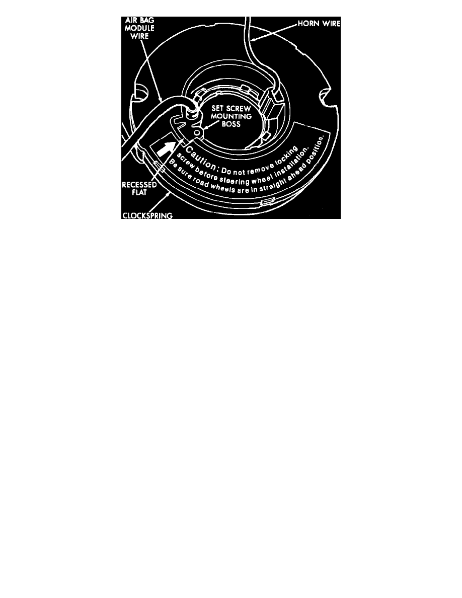
Fig. 90 Non-Auto-Locking Type Clockspring, (Chrysler Steering Column)
CENTERING
The following procedure must be used if the clockspring is not known to be properly positioned in order to prevent clockspring failure.
Two different types of clocksprings are used, one with a setscrew, the other with an automatic lock, which engages when the steering wheel is
removed. Automatic locking clocksprings can be identified by the lack of a setscrew and tether strap.
1.
Place front wheels in straight ahead position.
2.
Rotate clockspring rotor counterclockwise to the end of its travel.
3.
From this position, rotate clockspring rotor clockwise two full turns.
4.
On models equipped with non-auto-locking type clockspring, continue to turn rotor clockwise until setscrew mounting boss is aligned with
recessed flat on clockspring housing, Do not rotate more than 1/2 turn to align.
INSTALLATION
Obtain new clockspring assembly service kit containing clockspring assembly and lower two way connector. Ensure all parts are contained in kit.
1.
Tape new clockspring wire lead to wire that was left in steering column.
2.
Pull new clockspring wire lead down through column using wire in column.
3.
Once clockspring lead is through column, untape two wires, and insert clockspring lead terminals into connector.
4.
Install locking wedge and connect clockspring assembly to instrument panel wiring harness.
5.
Mount clockspring assembly to turn signal switch using two screws, and torque to 10-20 lb-in. If clockspring is not properly positioned, follow
procedure outlined under CENTERING prior to installing steering wheel.
6.
Install steering wheel and vibration damper (if equipped), making sure to pull horn lead through upper smaller hole and clockspring lead through
bottom larger hole.
7.
Index flats on hub of steering wheel with formations on inside of clockspring.
8.
Remove clockspring assembly locking screw and insert screw into steering wheel where it was stored, (if equipped), torque to 4 lb-in.
9.
Connect horn lead wire and clockspring lead wire to airbag module.
10.
Using a 10 mm thin wall socket, install airbag module and torque nuts to 80-100 lb-in.
11.
Do not connect battery ground cable. Refer to Air Bag Systems/Testing and Inspection/Procedures for proper procedure.