
Sprinter 2500 L5-2.7L DSL Turbo (2003)
Wiper Relay: Description and Operation
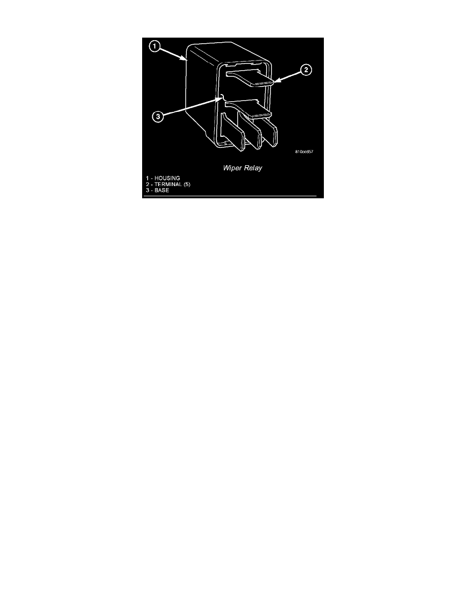
Wiper Relay
A wiper relay is standard equipment on all models. The wiper relay (or intermittent wipe relay) is located in a dedicated receptacle on the bottom left of
the fuse block on the underside of the steering column. The wiper relay is a conventional International Standards Organization (ISO) micro relay. Relays
conforming to the ISO specifications have common physical dimensions, current capacities, terminal patterns, and terminal functions. The relay is
contained within a small, rectangular, molded plastic housing. The relay is connected to all of the required inputs and outputs through the instrument
panel wire harness connector by five male spade-type terminals that extend from the bottom of the relay base. The ISO designation for each terminal is
molded into the base adjacent to the terminal. The ISO terminal designations are as follows:
-
30 (Common Feed) - This terminal is connected to the movable contact point of the relay.
-
85 (Coil Ground) - This terminal is connected to the ground feed side of the relay control coil.
-
86 (Coil Battery) - This terminal is connected to the battery feed side of the relay control coil.
-
87 (Normally Open) - This terminal is connected to the normally open fixed contact point of the relay.
-
87A (Normally Closed) - This terminal is connected to the normally closed fixed contact point of the relay.
The wiper relay cannot be adjusted or repaired. If the relay is damaged or faulty, it must be replaced.
The wiper relay (or intermittent wipe relay) is an electromechanical switch that uses a low current input from the intermittent wipe logic circuitry within
the fuse block underneath the steering column to control a high current output to the low speed brush of the wiper motor. The movable common feed
contact point is held against the fixed normally closed contact point by spring pressure. When the relay coil is energized, an electromagnetic field is
produced by the coil windings. This electromagnetic field draws the movable relay contact point away from the fixed normally closed contact point, and
holds it against the fixed normally open contact point. When the relay coil is de-energized, spring pressure returns the movable contact point back
against the fixed normally closed contact point. A resistor or diode is connected in parallel with the relay coil in the relay, and helps to dissipate voltage
spikes and electromagnetic interference that can be generated as the electromagnetic field of the relay coil collapses.
The wiper relay terminals are connected to the vehicle electrical system through a connector receptacle in the fuse block. The inputs and outputs of the
wiper relay include:
-
The common feed terminal (30) provides an output to the wiper motor low speed brush through the wiper control circuitry of the multi-function
switch on the steering column. When the wiper relay is de-energized, the common feed terminal is connected to the input of the relay normally
closed terminal (87). When the wiper relay is energized, the common feed terminal is connected to the input of the relay normally open terminal
(87A).
-
The coil ground terminal (85) is connected to battery current through a fused ignition switch output circuit whenever the ignition switch is in the
On position.
-
The coil battery terminal (86) is connected to the relay control output of the wiper, turn signals and engine start control module within the fuse
block through the wiper relay control circuit. This electronic circuitry controls the ground path for this circuit internally to energize or de-energize
the wiper relay control coil based upon its programming and inputs from the wiper and washer control circuitry of the multi-function switch, the
wiper motor park switch, and the ignition switch.
-
The normally open terminal (87) is connected to the output of the wiper motor park switch through the wiper motor park switch sense circuit. This
circuit can carry either battery current (wipers are not in park position) or ground (wipers are in park position), depending upon the status of the
wiper park switch.
-
The normally closed terminal (87A) is connected to battery current through a fused ignition switch output circuit whenever the ignition switch is in
the On position.
The wiper relay can be diagnosed using conventional diagnostic tools and methods.