
Sprinter 2500 V6-3.0L DSL Turbo VIN 45 (2007)
Headlamp Switch: Description and Operation
Headlamp Switch
Description
DESCRIPTION
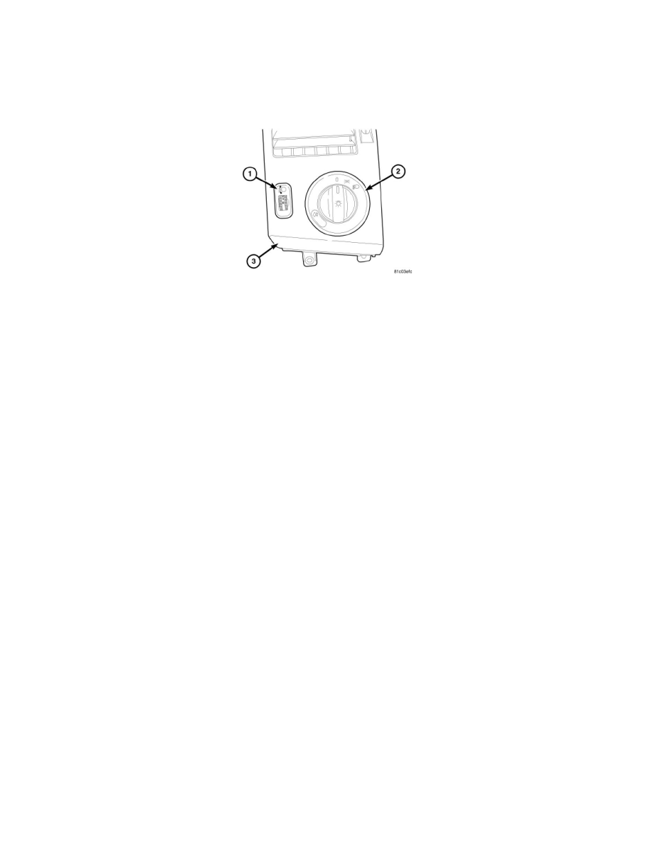
The headlamp switch (2) (also known as the Rotary Light Switch/RLS or light switch module) is located in the left outboard air outlet bezel (3) on the
instrument panel just outboard of the instrument cluster bezel. This switch is the primary driver control for the exterior lighting systems. Only the switch
bezel and rotary knob are visible on the outer surface of the air outlet bezel. The black plastic switch bezel is labeled at each detent position with either
white text or an International Control and Display Symbol icon, which clearly identify its many functions. The switch knob is marked with the
International Control and Display Symbol icon for Master Lighting Switch.
The black, molded plastic switch housing and bezel encloses the switch rotary knob mechanism and the light switch circuitry including the switch
contacts. The switch circuitry includes integral internal backlighting elements, which illuminate the switch markings for visibility when the exterior
lighting is turned ON as well as Light Emitting Diode (LED) units to indicate the switching status of certain exterior lighting features. A connector
receptacle is integral to the back of the switch housing. Two molded plastic mounting features integral to the switch housing are used to secure the switch
within a receptacle integral to the back side of the air outlet bezel with two screws. The switch is connected to the vehicle electrical system through a
dedicated take out and connector of the vehicle wire harness.
Several versions of the headlamp switch are available, which vary with the optional exterior lighting features on the vehicle. The headlamp switch cannot
be adjusted or repaired and, if ineffective or damaged, the entire switch unit must be replaced.
Operation
OPERATION
The headlamp switch (also known as the Rotary Light Switch/RLS or light switch module) receives battery voltage at all times. The switch receives a
path to ground at all times through the vehicle wire harness. The only output from the switch is a voltage signal that it provides to the Body Control
Module (BCM) (also known as the Signal Acquisition and Actuation Module/SAM). Each switch position selects a different tap on a series resistor
within the switch to provide a different voltage signal to the BCM and the BCM controls the exterior lighting features accordingly.
The headlamp switch as well as the hard wired inputs and outputs of the switch may be diagnosed using conventional diagnostic tools and procedures.
Refer to the appropriate wiring information. However, conventional diagnostic methods will not prove conclusive in the diagnosis of the electronic
controls and communication that provide some features of the exterior lighting system. Proper diagnosis of the BCM, the CAN data bus and the
electronic communication related to exterior lighting system operation requires the use of a diagnostic scan tool. Refer to the appropriate diagnostic
information.