
Sprinter 3500 L5-2.7L DSL Turbo (2004)
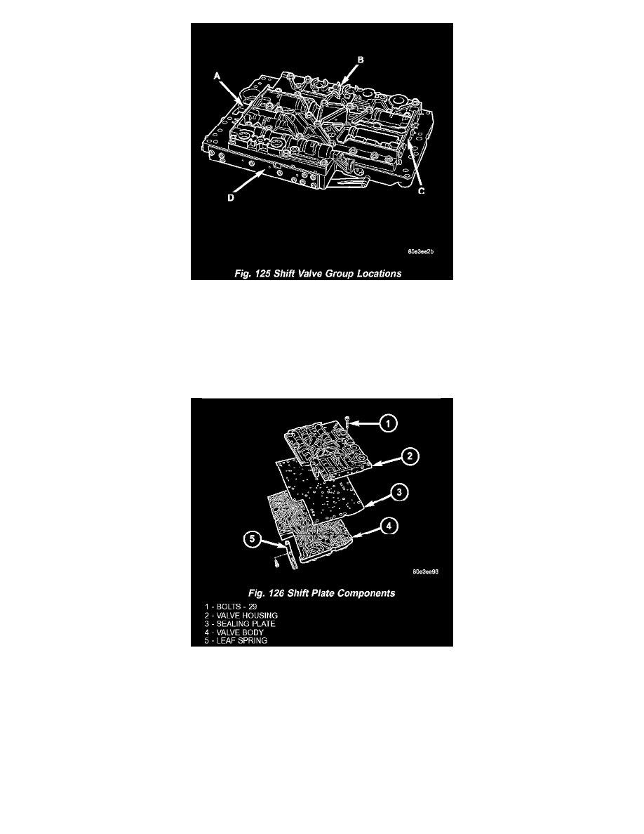
8. Note the locations of the major shift valve group components for assembly reference. (Fig. 125)
A Operating and Lubricating Pressure Regulating valves and 2 - 3 Overlap valve
B 1 - 2 / 4 - 5 Shift Group and Shift, Shift Valve, and Regulating Valve Pressure Regulating Valves
C 3 - 4 Shift Group
D 2 - 3 Shift Group, TCC Lock up, and B2 Regulating Valves
NOTE: Pay great attention to cleanliness for all work on the shift plate. Fluffy cloths must not be used. Leather cloths are particularly good. After
dismantling, all parts must be washed and blown out with compressed air, noting that parts may be blown away.
9. Unbolt leaf spring (5) (Fig. 126).
10. Unscrew Torx (R) bolts (1) (Fig. 126).
11. Remove valve housing (2) from valve body (4) (Fig. 126).
12. Remove sealing plate (3).