
Sprinter 3500 V6-3.0L DSL Turbo (2008)
Piston: Procedures
Piston and Connecting Rod - Inspection
INSPECTION
PISTONS
1. Check piston pin bores in piston for roundness. Make 3 checks at 120° intervals. Maximum out of roundness.020 mm (.0008 in.).
2. The piston diameter should be measured approximately 10mm (.394 in.) up from the base.
3. Skirt wear should not exceed 0.1 mm (.00039 in.).
4. The clearance between the cylinder liner and piston should not exceed 0.010-0.022 mm (.0003 -.0008 in.).
PISTON PINS
1. Measure the diameter of piston pin in the center and both ends. Refer to the engine specification chart See: Specifications/Engine Specifications.
CONNECTING RODS
CAUTION: Connecting rods must be replaced once the end caps are loosened. All six must have the same weight and the same number.
Replacement connecting rods will only be supplied in sets of six. When assembling the connecting rod, be sure to paint mark or scribe mark
each of the connecting rods and caps before installation, for alignment purposes later.
NOTE: Do Not lubricate the new connecting rod bolts. They are already coated with a anti scuff treatment.
Connecting rods are supplied in sets of six since they all must be of the same weight category. Max allowable weight difference is 5 gr.
1. Assemble bearing shells and bearing caps to their respective connecting rods ensuring that the serrations on the cap and reference marks are
aligned.
2. Tighten connecting cap bolts to 20 Nm (15 ft. lbs.).
3. Without loosening connecting rod bolts, tighten all bolts to 40 Nm (30 ft.lbs.).
4. Using a torque angle gauge, tighten each bolt an additional 90°.
Piston Ring Fitting
PISTON RING FITTING
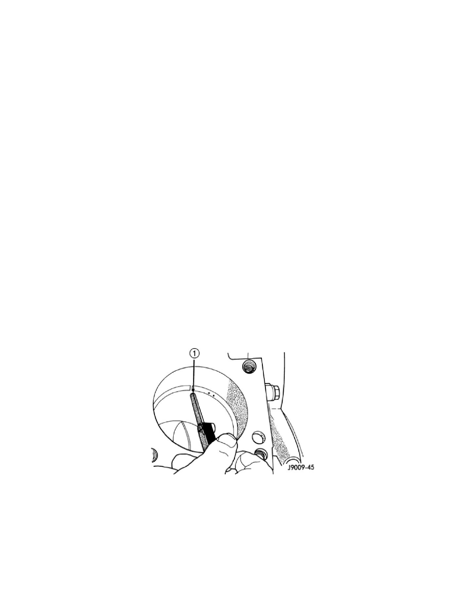
1. Wipe cylinder bore clean. Insert ring and push down with piston to ensure it is square in bore. The ring gap measurement must be made with the
ring positioning at least 12 mm (0.50 in.) from bottom of cylinder bore. Check gap with feeler gauge (1). Top compression ring gap.40 to.55mm
(.015in to.0217 in.). Second compression ring gap.25mm to.50mm (.0099 to.0197 in.). Oil control ring gap.20 to.40mm (.0079 to.0158 in.).
2. If ring gaps exceed dimension given, new rings, piston and cylinder boring may be necessary. Keep piston rings in piston sets.