
Sprinter 3500 V6-3.0L DSL Turbo (2008)
1. Verify the problem.
2. Verify any related symptoms. Do this by performing operational checks on components that are in the same circuit. Refer to the wiring diagrams.
3. Analyze the symptoms. Use the wiring diagrams to determine what the circuit is doing, where the problem most likely is occurring and where the
diagnosis will continue.
4. Isolate the problem area.
5. Repair the problem area.
6. Verify the proper operation. For this step, check for proper operation of all items on the repaired circuit. Refer to the wiring diagrams.
Electrostatic Discharge (ESD) Sensitive Devices
ELECTROSTATIC DISCHARGE (ESD) SENSITIVE DEVICES
All ESD sensitive components are solid state and a symbol is used to indicate this. When handling any component with this symbol, comply with the
following procedures to reduce the possibility of electrostatic charge build up on the body and inadvertent discharge into the component. If it is not
known whether the part is ESD sensitive, assume that it is.
1. Always touch a known good ground before handling the part. This should be repeated while handling the part and more frequently after sliding
across a seat, sitting down from a standing position, or walking a distance.
2. Avoid touching electrical terminals of the part, unless instructed to do so by a written procedure.
3. When using a voltmeter, be sure to connect the ground lead first.
4. Do not remove the part form it's protective packing until it is time to install the part.
5. Before removing the part from it's package, ground the package to a known good ground on the vehicle.
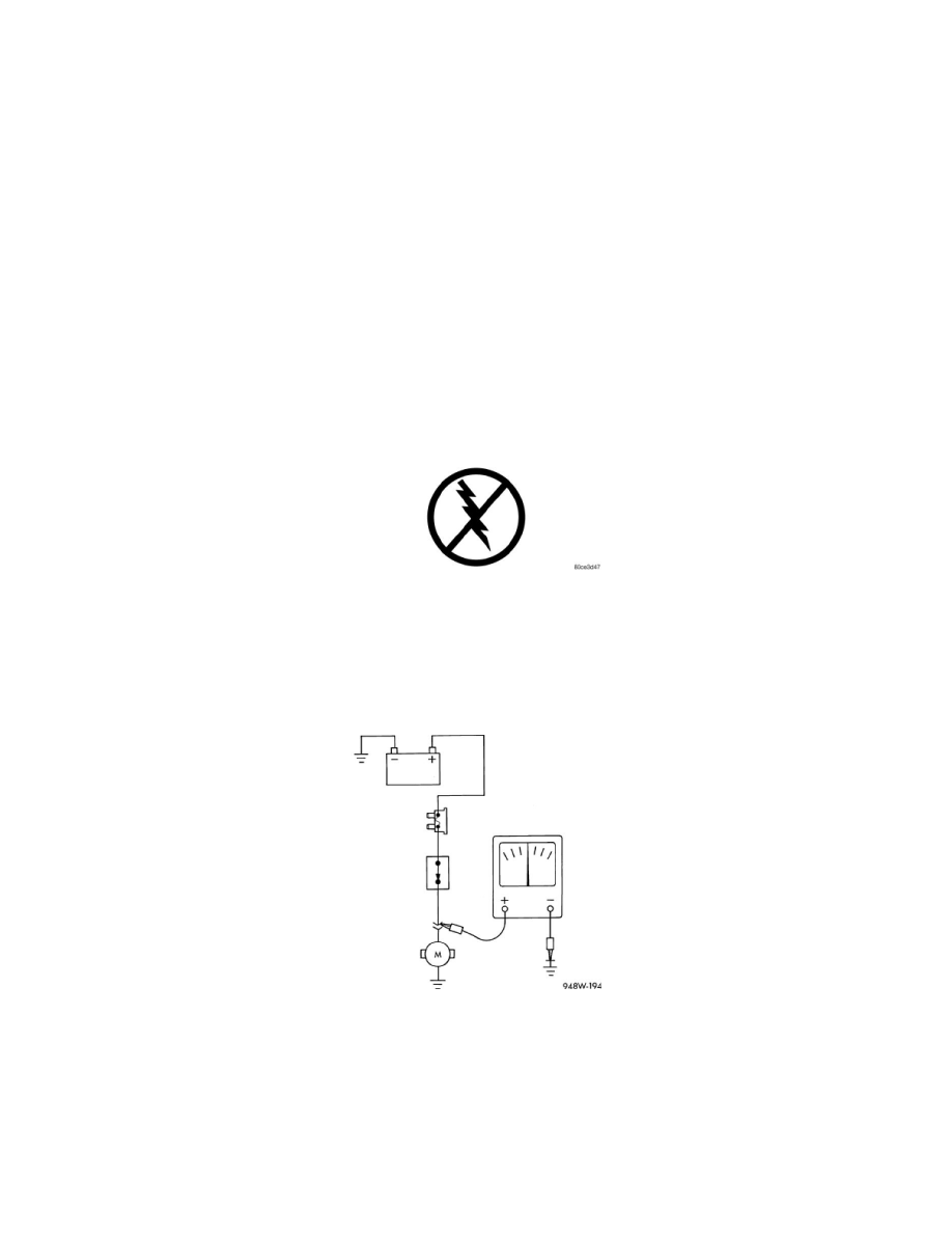
Testing For Voltage Potential
TESTING FOR VOLTAGE POTENTIAL
1. Connect the ground lead of a voltmeter to a known good ground.
2. Connect the other lead of the voltmeter to the selected test point. The vehicle ignition may need to be turned ON to check voltage. Refer to the
appropriate test procedure.
Testing For Continuity
TESTING FOR CONTINUITY
1. Remove the fuse for the circuit being checked or, disconnect the battery.
2. Connect one lead of the ohmmeter to one side of the circuit being tested.
3. Connect the other lead to the other end of the circuit being tested. Low or no resistance means good continuity.