
Sprinter 3500 V6-3.0L DSL Turbo (2008)
Splice diagrams show the entire splice and provide references to other sections the splices serves. Section 8W-70 only contains splice diagrams that are
not shown in their entirety somewhere else in the wiring diagrams.
Section 8W-80 shows each connector and the circuits involved with that connector. The connectors are identified using the name/number on the diagram
pages.
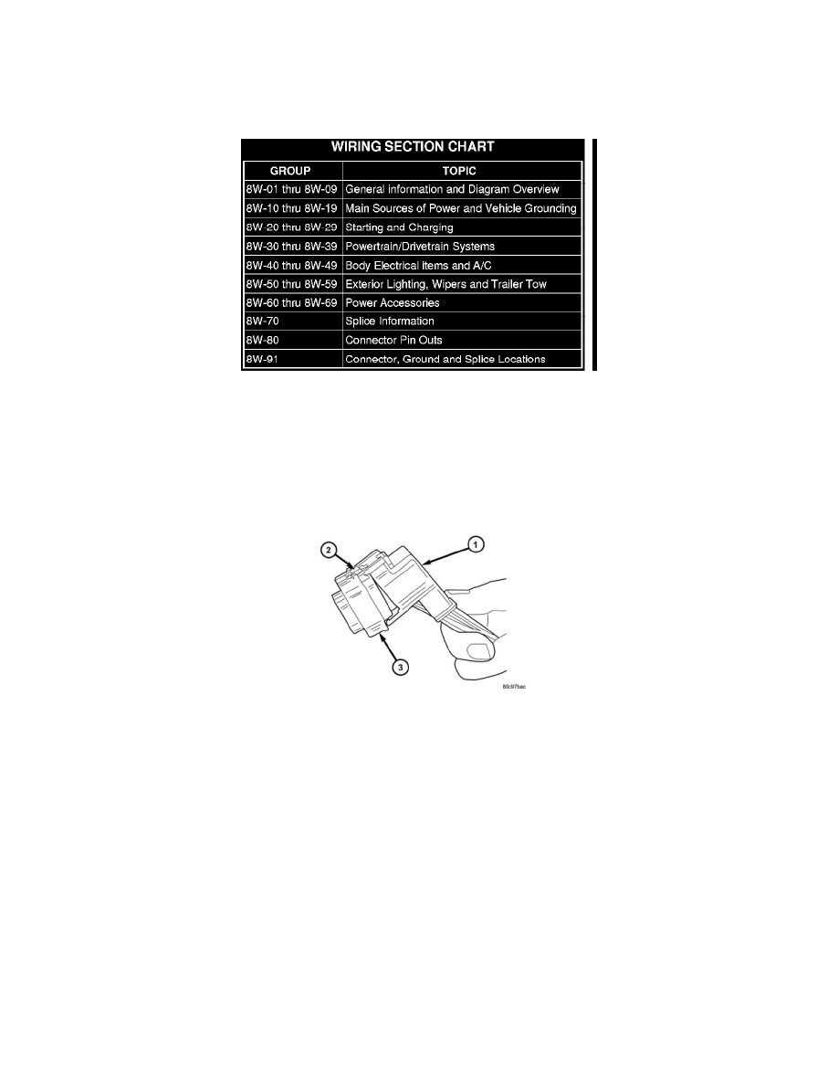
Removal
REMOVAL
1. Disconnect battery.
2. Release Connector Lock.
3. Disconnect the connector being repaired from its mating half/component.
4. Remove the dress cover (if applicable).
5. Release the Secondary Terminal Lock, if required.
6. Position the connector locking finger away from the terminal using the proper special tool. Pull on the wire to remove the terminal from the
connector.
Installation
INSTALLATION
1. Insert the removed terminal in the same cavity on the repair connector.
2. Repeat steps for each terminal in the connector, being sure that all wires are inserted into the proper cavities. For additional connector pin-out
identification, refer to the wiring diagrams.
3. When the connector is re-assembled, the secondary terminal lock must be placed in the locked position to prevent terminal push out.
4. Replace dress cover (if applicable).
5. Connect connector to its mating half/component.
6. Connect battery and test all affected systems.
Removal
REMOVAL
1. Disconnect the battery.
2. Locate the diode in the harness, and remove the protective covering.
3. Remove the diode from the harness, pay attention to the current flow direction.