
Sprinter 3500 V6-3.0L DSL Turbo (2008)
Front Cross-Member: Service and Repair
Installation
INSTALLATION
1. Raise crossmember assembly into place onto the vehicle and line up the crossmember with the marks made during removal.
NOTE: The steering gear universal joint must be guided in at the same time as the crossmember is fitted.
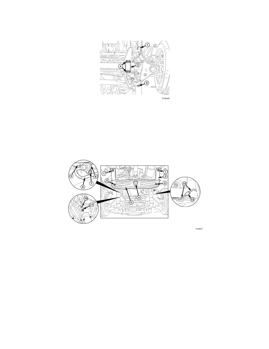
2. Install the bolts (1, 3).
3. Tighten bolts (3) to 172 Nm (127 ft. lbs.)
4. Tighten bolts (1) to;
-
120 Nm (90 ft. lbs.).
-
Turn an additional 270 degrees.
5. Install the bolts (1) and tighten to 172 Nm (127 ft. lbs.).
6. Install the engine mount bolts and tighten to 58 Nm (43 ft. lbs.).
7. Install the transmission crossmember (5) and install the bolts (3, 4)
8. Tighten the crossmember bolts (3) to 58 Nm (43 ft. lbs.).
9. Remove the transmission support.
10. Install the bolt (4) and tighten to;
-
M8 = 30 Nm (22 ft. lbs.).
-
M10 = 58 Nm (43 ft. lbs.).
11. Install a new gasket for the power steering gear lines and secure lines to the steering gear. Tighten the lines (8) to 18 Nm (13 ft. lbs.)
12. Attach power steering high pressure (8) and return lines to the frame-type integral support (2).
13. Install the mounting clamp and install the nut.
14. Attach the high pressure line (8) and clamp (6) and install the nut (7).
15. Clip the battery ground line (9) to the bracket.
16. Install the universal joint (10) and install the bolt (11).
17. Connect the brake lines (12) and connect the bolted connection (13).
18. Connect the rpm sensor electrical connectors.
19. Connect the brake pad wear indicator electrical connectors.
20. Using a floor jack or equivalent, raise the shock absorbers up into the body and install the mounting bolts.
21. Tighten the shock mounting bolts to;