
Sprinter 3500 V6-3.0L DSL Turbo VIN 45 (2007)
ABS Light: Description and Operation
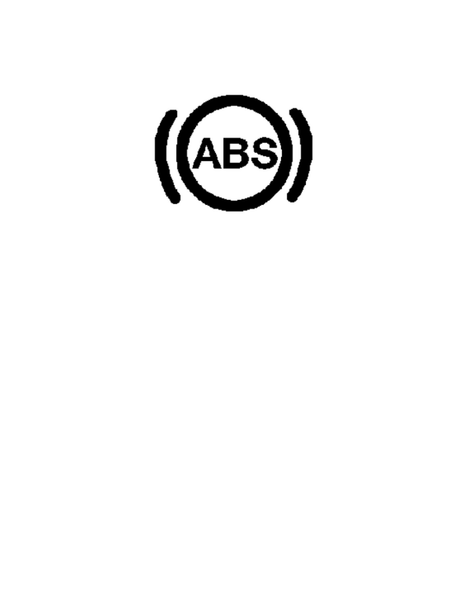
ABS Indicator
Description
DESCRIPTION
An Anti-lock Brake System (ABS) indicator is standard equipment on all instrument clusters. This indicator is located near the top of the cluster overlay,
between the speedometer and the multi-function indicator display. On vehicles equipped with the optional steering wheel buttons, illumination of this
indicator may also be accompanied by the display of certain textual messages in the cluster multi-function display.
The ABS indicator consists of a stencil-like cutout of the International Control and Display Symbol icon for Failure of Anti-lock Braking System in
the opaque layer of the instrument cluster overlay. The dark outer layer of the overlay prevents the indicator from being clearly visible when it is not
illuminated. An amber Light Emitting Diode (LED) behind the cutout in the opaque layer of the overlay causes the indicator to appear in amber through
the translucent outer layer of the overlay when it is illuminated from behind by the LED, which is soldered onto the instrument cluster electronic circuit
board.
The ABS indicator is serviced as a unit with the instrument cluster.
Operation
OPERATION
The ABS indicator gives an indication to the vehicle operator when the ABS system, or a circuit or component of the system is ineffective. This indicator
is controlled by a transistor on the instrument cluster circuit board based upon cluster programming and electronic messages received by the cluster over
the Controller Area Network (CAN) data bus from the Controller Antilock Brake (CAB) (also known as the Antilock Brake System/ABS or Electronic
Stability Program/ESP controller).
The ABS indicator Light Emitting Diode (LED) is completely controlled by the instrument cluster logic circuit, and that logic will only allow this
indicator to operate when the instrument cluster detects that the ignition switch is in the ON position. Therefore, the LED will always be OFF when the
ignition switch is in any position except ON. The LED only illuminates when it is provided a path to ground by the instrument cluster transistor. The
instrument cluster will turn ON the ABS indicator for the following reasons:
-
Bulb Test - Each time the ignition switch is turned to the ON position the ABS indicator is illuminated briefly as a bulb test. The entire bulb test is
a function of the CAB.
-
ABS Indicator Lamp-On Message - Each time the cluster receives an electronic ABS indicator lamp-ON message from the CAB indicating that
the ABS system has been deactivated, the ABS indicator will be illuminated. The indicator remains illuminated until the cluster receives a
lamp-OFF message from the CAB, or until the ignition switch is turned to the OFF position, whichever occurs first. On vehicles equipped with the
optional steering wheel buttons, each time the cluster receives an electronic ABS indicator lamp-ON message from the CAB, the ABS indicator
will be illuminated and a Visit workshop or unavailable textual message will appear within the cluster multi-function display. The indicator and
textual message remain displayed until the cluster receives a lamp-OFF message from the CAB, or until the ignition switch is turned to the OFF
position, whichever occurs first.
The CAB continually monitors the ABS system circuits and sensors to decide whether the system is in good operating condition. The CAB then sends
the proper lamp-ON or lamp-OFF messages to the ElectroMechanical Instrument Cluster (EMIC) (also known as the Cab Compartment Node/CCN or
KOMBI). If the CAB sends a lamp-ON message after the bulb test, it indicates that the CAB has detected a system malfunction or that the ABS system
has become ineffective. The CAB will store a Diagnostic Trouble Code (DTC) for any malfunction it detects.