
Sprinter 3500 V6-3.0L DSL Turbo VIN 45 (2007)
The EVIC system is comprised of several different components. Those components are:
-
Instrument Cluster (sometimes referred to as the EMIC or Cab Compartment Node [CCN])
-
Steering Wheel Function Buttons
-
Ambient Temperature Sensor
-
Controller Area Network (CAN) Data Bus
-
Body Control Module (BCM) (also known as the Signal Acquisition and Actuation Module/SAM)
The EVIC display is part of the Instrument Cluster assembly and is not serviced as a separate component. If the display is inoperative the complete
Instrument Cluster assembly must be replaced.
Operation
OPERATION
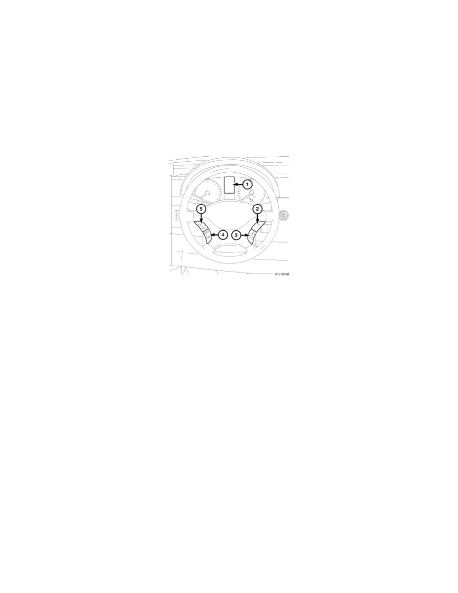
The Electronic Vehicle Information Center (EVIC) features dual multi-function indicator Organic Light Emitting Diode (OLED) units. The dual OLED
display units (1) are located in the center of the ElectroMechanical Instrument Cluster (EMIC). The EVIC functions and settings are controlled using
both the EVIC function buttons (2, 3, 4 & 5) located on the steering wheel and the instrument cluster pushbuttons.
The microprocessor-based EMIC hardware and software uses various inputs to control the EVIC functions of the cluster. Some of these inputs are hard
wired, but most are in the form of electronic messages that are transmitted by other electronic modules over the Controller Area Network (CAN) data bus
network.
The EMIC circuitry operates on battery current received through a fused B(+) fuse on a non-switched fused B(+) circuit, and monitors the electronic
ignition switch status messages received from the Electronic Ignition Switch (EIS) (also known as the Electronic Ignition Switch/Central
Gateway/EIS/CGW or EZS) over the CAN data bus. This arrangement allows the EMIC to provide some features regardless of the ignition switch
position, while other features will operate only with the ignition switch in the ON or START positions. The EMIC circuitry is grounded through a ground
circuit and take out of the vehicle wire harness with an eyelet terminal connector that is secured to a stud by a nut at a ground location on the vehicle
sheet metal structure.
Proper diagnosis of the EMIC, the CAN data bus or the electronic message inputs to and outputs from the EMIC, as well as the retrieval or erasure of a
Diagnostic Trouble Code (DTC) requires the use of a diagnostic scan tool. Refer to the appropriate diagnostic information.
The EVIC function buttons are used to operate the different functions of the EVIC system. Pressing and releasing the PLUS or MINUS buttons (2)
Selects a EVIC submenu or adjusts the volume. The telephone buttons (3) are used to control the features of the UConnect hands-free communication
system. Pressing and releasing the PAGE FORWARD or PAGE BACKWARDS buttons (4) allows the operator to jump from one EVIC menu to
another. Pressing and releasing the UP ARROW or DOWN ARROW buttons (5) allows the operator to jump from one EVIC submenu to another.
EVIC DISPLAY MODES
The table below shows the different EVIC menus and their individual functions.