
SRT-4 L4-2.4L Turbo VIN S (2004)
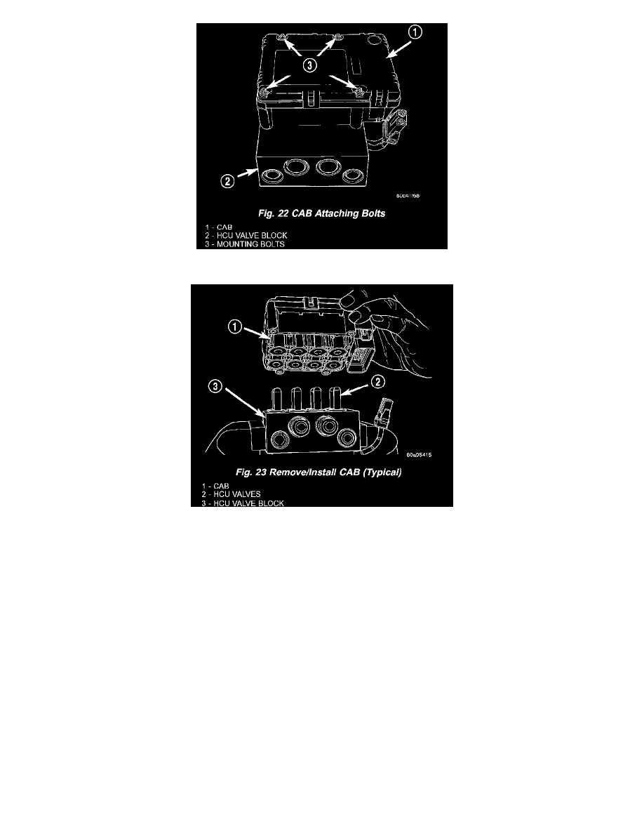
2. Remove the 4 bolts attaching the CAB to the HCU (Fig. 22).
3. Remove the CAB from the HCU (Fig. 23).
ASSEMBLY - ICU
1. Install the CAB on the HCU (Fig. 23).
2. Install the 4 bolts mounting the CAB to the HCU (Fig. 22). Tighten the CAB mounting bolts to a torque of 2 Nm (17 inch lbs.).
3. Plug the pump/motor wiring harness into the CAB (Fig. 21).
4. Install the ICU in the vehicle.
INSTALLATION - ICU
1. Install the ICU onto its mounting bracket.
2. Install the 3 bolts attaching the ICU to the mounting bracket (Fig. 20). Tighten the 3 mounting bolts to a torque of 11 Nm (97 inch lbs.).
3. Install the four brake tubes going to the brakes into their respective outlet ports on the ICU HCU (Fig. 18). Using a crow foot on a torque wrench,
tighten the four brake tube nuts to a torque of 17 Nm (145 inch lbs.).
NOTE: When installing the brake tubes from the master cylinder on the HCU, the brake tube with the small tube nut is to be installed in the
forward-most port on the HCU with the small end going toward the master cylinder secondary port.
4. Install the primary and secondary brake tubes from the master cylinder onto the HCU (Fig. 18). Do not completely tighten the primary and
secondary tubes at this time.
5. Connect the primary and secondary brake tubes to the master cylinder ports (Fig. 18).
6. Using a crow foot on a torque wrench, tighten the primary and secondary brake tube nuts at both the master cylinder and HCU to a torque of 17
Nm (145 inch lbs.).
CAUTION: Before installing the 24-way connector in the CAB, be sure the seal is properly installed in the connector.