
SRT-4 L4-2.4L Turbo VIN S (2004)
Compressor Clutch Relay: Description and Operation
The A/C compressor clutch relay is a International Standards Organization (ISO) micro-relay. Relays conforming to the ISO specifications have common
physical dimensions, current capacities, terminal patterns, and terminal functions. The ISO micro-relay terminal functions are the same as a conventional
ISO relay. However, the ISO micro-relay terminal pattern (or footprint) is different, the current capacity is lower, and the physical dimensions are
smaller than those of the conventional ISO relay. The A/C compressor clutch relay is located in the Power Distribution Center (PDC) in the engine
compartment. See the fuse and relay layout label affixed to the inside surface of the PDC cover for A/C compressor clutch relay identification and
location.
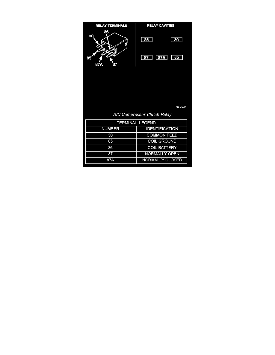
The black, molded plastic case is the most visible component of the A/C compressor clutch relay. Five male spade-type terminals extend from the bottom
of the base to connect the relay to the vehicle electrical system, and the ISO designation for each terminal is molded into the base adjacent to each
terminal. The ISO terminal designations are as follows:
-
30 (Common Feed) - This terminal is connected to the movable contact point of the relay.
-
85 (Coil Ground) - This terminal is connected to the ground feed side of the relay control coil.
-
86 (Coil Battery) - This terminal is connected to the battery feed side of the relay control coil.
-
87 (Normally Open) - This terminal is connected to the normally open fixed contact point of the relay.
-
87A (Normally Closed) - This terminal is connected to the normally closed fixed contact point of the relay.
The factory-installed A/C compressor clutch relay cannot be adjusted or repaired. If the relay is damaged or faulty, it must be replaced.
The A/C compressor clutch relay is an electromechanical switch that uses a low current input from the Powertrain Control Module (PCM) to control the
high current output to the Compressor clutch electromagnetic coil. The movable common feed contact point is held against the fixed normally closed
contact point by spring pressure. When the relay coil is energized, an electromagnetic field is produced by the coil windings. This electromagnetic field
draws the movable relay contact point away from the fixed normally closed contact point, and holds it against the fixed normally open contact point.
When the relay coil is de-energized, spring pressure returns the movable contact point back against the fixed normally closed contact point. The resistor
or diode is connected in parallel with the relay coil in the relay, and helps to dissipate voltage spikes and electromagnetic interference that can be
generated as the electromagnetic field of the relay coil collapses.
The A/C compressor clutch relay terminals are connected to the vehicle electrical system through a receptacle in the PDC. The inputs and outputs of the
A/C compressor clutch relay include:
-
The common feed terminal (30) receives a battery current input from a fuse in the PDC through a fused B(+) circuit at all times.
-
The coil ground terminal (85) receives a ground input from the PCM through the A/C compressor clutch relay control circuit only when the PCM
electronically pulls the control circuit to ground.
-
The coil battery terminal (86) receives a battery current input from a fuse in the fuse block module through a fused ignition switch output
(run-start) circuit only when the ignition switch is in the On or Start positions.
-
The normally open terminal (87) provides a battery current output to the compressor clutch coil through the A/C compressor clutch relay output