
SRT-4 L4-2.4L Turbo VIN S (2004)
Combination Switch: Description and Operation
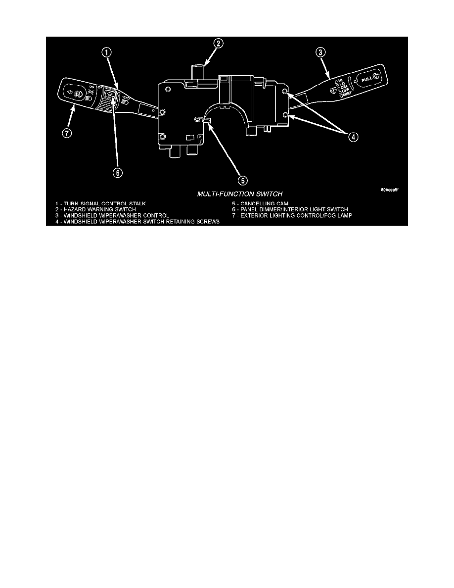
The multi-function switch is secured to the upper steering column housing at the top of the steering column, just below the steering wheel. The visible
parts of the multi-function switch are the turn signal control stalk that extends through a dedicated opening in the left side of the upper steering column
shrouds, the windshield wiper/washer, exterior lighting control stalk that extends through a dedicated opening in the right upper steering column shrouds,
the hazard warning switch push button that protrudes through an opening in the upper steering column shroud on the top of the steering column. The
remainder of the switch, its mounting provisions, and its electrical connections are all concealed beneath the steering column shrouds. The multi-function
switch control stalk has both nomenclature and International Control and Display Symbol graphics applied to it, which identify its many functions. An
International Control and Display Symbol icon for "Hazard Warning" is applied to the top of the hazard warning switch push button.
The switch housing and its controls are constructed of molded black plastic. A connector receptacle with up to twenty terminals is located on the back of
the switch housing and connects the switch to the vehicle electrical system through a take out and connector of the instrument panel wire harness.
The multi-function switch supports the following functions and features:
-
Continuous Wipe Modes - The control knob of the multi-function switch provides two continuous wipe switch positions, low speed or high speed.
-
Intermittent Wipe Mode - The control knob of the multi-function switch provides an intermittent wipe mode with multiple delay interval positions.
-
Washer Mode - A button on the end of the control stalk of the multi-function switch provides washer system operation when the button is
depressed towards the steering column.
-
Hazard Warning Control - The internal circuitry and hardware of the multi-function switch provide detent switching for activation and deactivation
of the hazard warning system.
-
Exterior Lighting Control - The internal circuitry and hardware of the multi-function switch provide for activation and deactivation of exterior
lighting.
-
Headlamp Beam Selection - The internal circuitry and hardware of the multi-function switch provide detent switching for selection of the
headlamp high or low beams.
-
Headlamp Optical Horn - The internal circuitry and hardware of the multi-function switch includes momentary switching of the headlamp high
beam circuits to provide an optical horn feature (sometimes referred to as flash-to-pass), which allows the vehicle operator to momentarily flash
the headlamp high beams as an optical signalling device.
HAZARD WARNING SYSTEM
The hazard warning system is actuated by a push button located in the multi-function switch on the top of the steering column between the steering wheel
and the instrument panel. The hazard switch is identified with a double triangle on front of the button.
The hazard warning system allows the vehicle operator to provide the drivers of other vehicles in near proximity an optical indication that the vehicle is
disabled or is an obstacle to Traffic flow. Unlike the turn signal system, the hazard warning system has battery current at all times, regardless of ignition
switch position.
The multi-function switch uses conventionally switched outputs and a variable resistor to control the many functions and features it provides using hard
wired circuitry. The switch is grounded at all times through a single wire take out with an eyelet terminal connector of the instrument panel wire harness
that is secured by a nut to a ground stud located on the instrument panel armature, just above and to the left of the glove box opening. When the ignition
switch is in the ACCESSORY or ON positions, battery current from a fuse in the Junction Block (JB) is provided through a fused ignition switch output
(RUN/ACC) circuit. Following are descriptions of the how the multi-function switch operates to control the many functions and features it provides: