
SRT-4 L4-2.4L Turbo VIN S (2004)
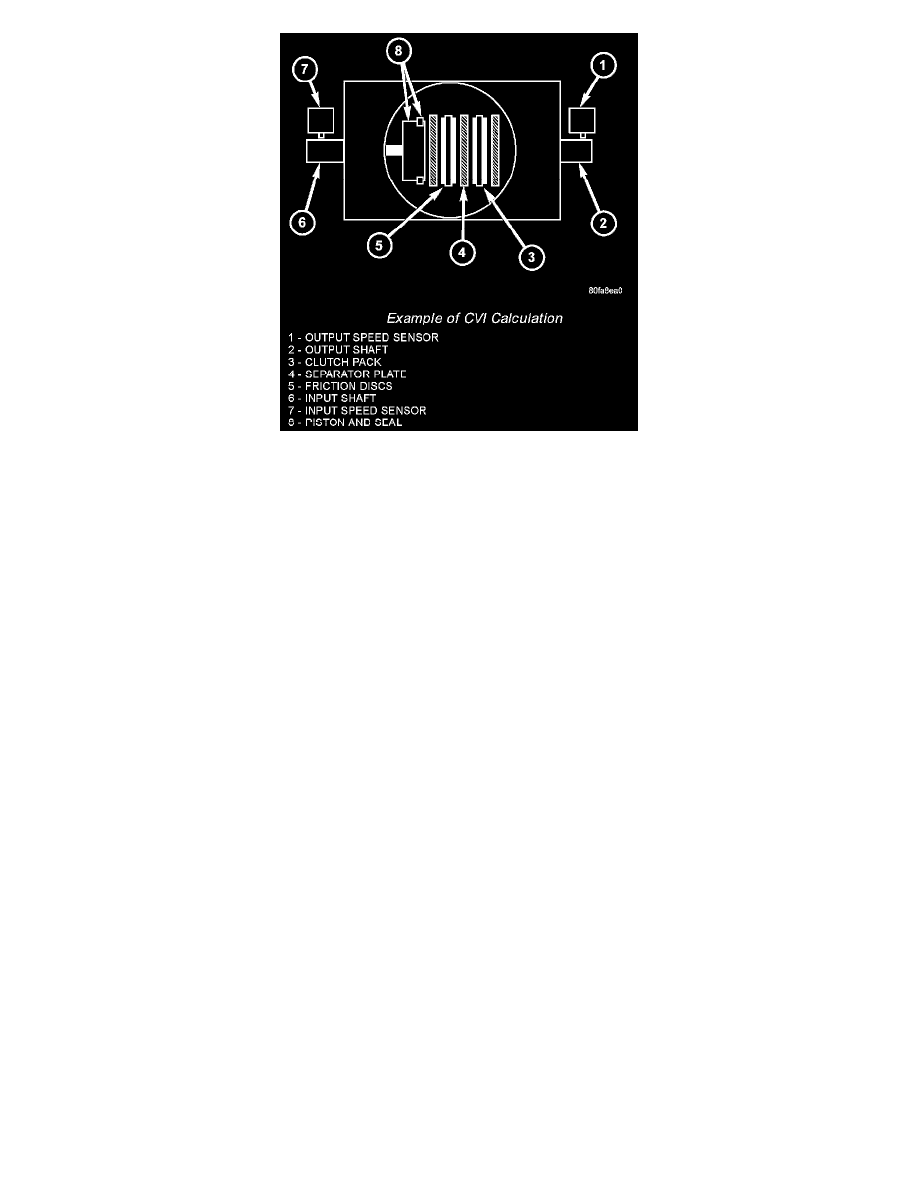
Example Of CVI Calculation
By comparing the two inputs, the PCM can determine transaxle gear ratio. This is important to the CM calculation because the PCM determines CVIs by
monitoring how long it takes for a gear change to occur.
Gear ratios can be determined by using the DRBIII(R) Scan Tool and reading the Input/Output Speed Sensor values in the "Monitors" display. Gear ratio
can be obtained by dividing the Input Speed Sensor value by the Output Speed Sensor value.
For example, if the input shaft is rotating at 1000 rpm and the output shaft is rotating at 500 rpm, then the PCM can determine that the gear ratio is 2:1.
In direct drive (3rd gear), the gear ratio changes to 1:1. The gear ratio changes as clutches are applied and released. By monitoring the length of time it
takes for the gear ratio to change following a shift request, the PCM can determine the volume of fluid used to apply or release a friction element.
The volume of transmission fluid needed to apply the friction elements are continuously updated for adaptive controls. As friction material wears, the
volume of fluid need to apply the element increases.
Certain mechanical problems within the clutch assemblies (broken return springs, out of position snap rings, excessive clutch pack clearance, improper
assembly, etc.) can cause inadequate or out-of-range clutch volumes. Also, defective Input/Output Speed
TRANSMISSION SHIFT SCHEDULES
The PCM is programmed to allow it to select a variety of shift schedules. Shift schedule selection is dependent on the following:
-
Shift lever position
-
Throttle position
-
Engine load
-
Fluid temperature
-
Software calibration level
As driving conditions change, the PCM appropriately adjusts the shift schedule. Refer to the following chart to determine the appropriate operation
expected, depending on driving conditions.