
Stealth V6-2972cc 3.0L SOHC (1995)
Engine Control Module Connector Terminal Configuration
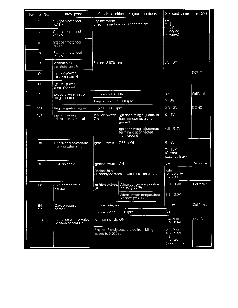
2. Insert the very thin probe from the wire side into contact with each of the terminals of the Engine Control Module (ECM) connector and check the
voltage, while referring to the check chart.
NOTES:
1. Measure a voltage with the ECM connector connected.
2. Measure the voltage between each terminal and the No. 26 terminal (ground terminal).
3. Withdraw the ECM for easier access to the connector terminals.
4. The inspection need not be performed in the order of the chart.