
Stealth ES V6-2972cc 3.0L DOHC (1991)
Variable Induction Position Sensor: Testing and Inspection
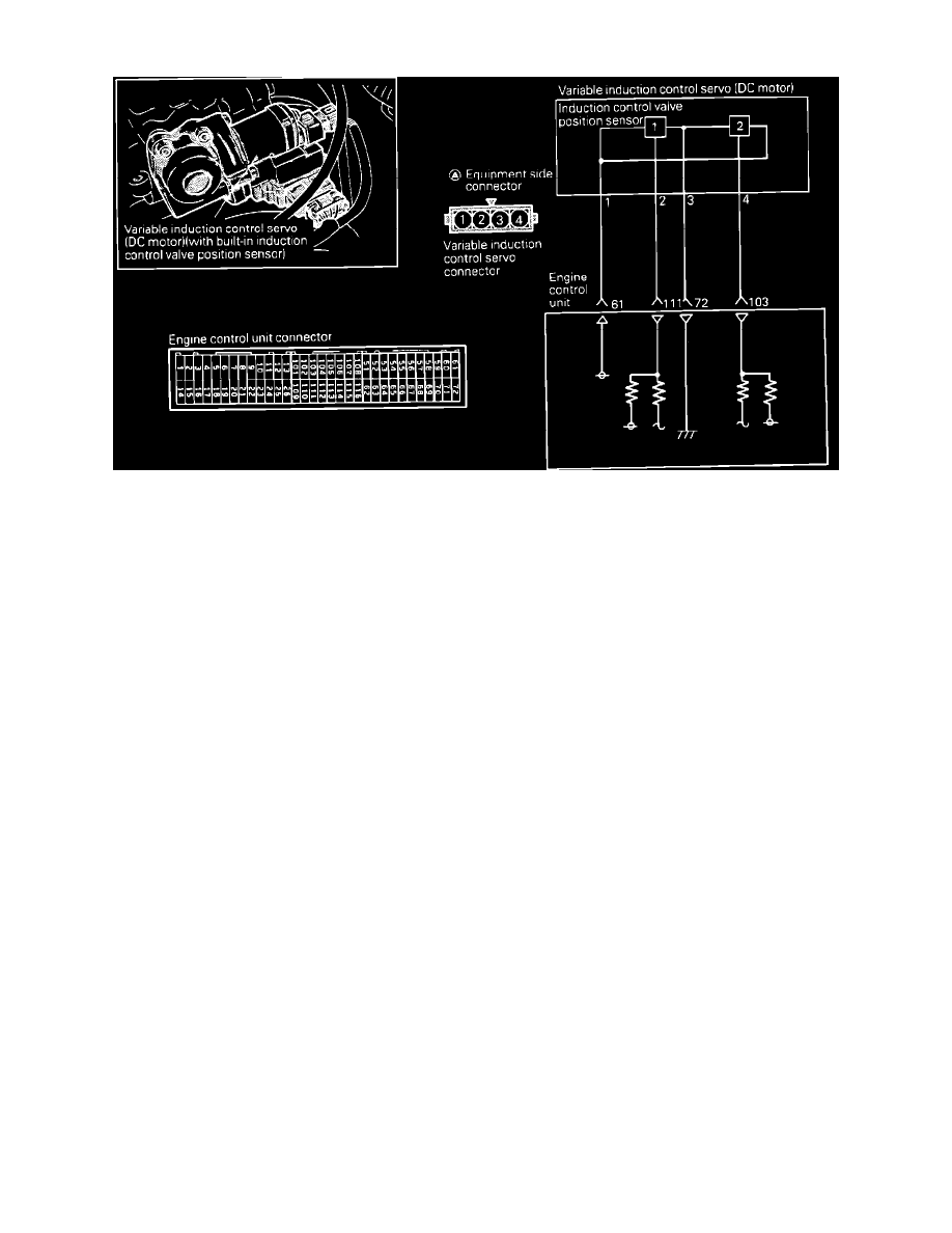
Induction Control Valve Position Sensor Circuit
COMPONENT TEST
Testing procedures for the induction control valve position sensor are not provided. If the following harness test procedure is followed, the sensor
can be tested by process of elimination.
HARNESS TESTING PROCEDURE:
1. Disconnect the induction control valve position sensor harness connector.
2. Turn the ignition switch to "ON" position.
3. Using a voltmeter, measure the voltage between the sensor harness connector terminal 1 and ground.
Voltage:
4.8 - 5.2 Volts.
4. Using an ohmmeter, check for continuity between sensor harness connector terminal 3 and ground.
Continuity:
Should exist.
5. Using a voltmeter, measure the voltage between ground and sensor harness connector terminals 2 and 4.
Voltage:
4.8 - 5.2 Volts.
If any of the previous tests produce unsatisfactory results, the harness will need to be repaired or replaced. Once repairs have been completed, clear
the trouble codes and road test the vehicle to confirm that the repair has corrected the problem and the code doesn't return.
If the same trouble code reoccurs, it is possible that there is an intermittent failure of the component or the ECM. Check for looseness at all harness
junctions and test for an intermittent failure. If no intermittents are found, replace the sensor and recheck.