
Stealth R/T V6-2972cc 3.0L DOHC (1991)
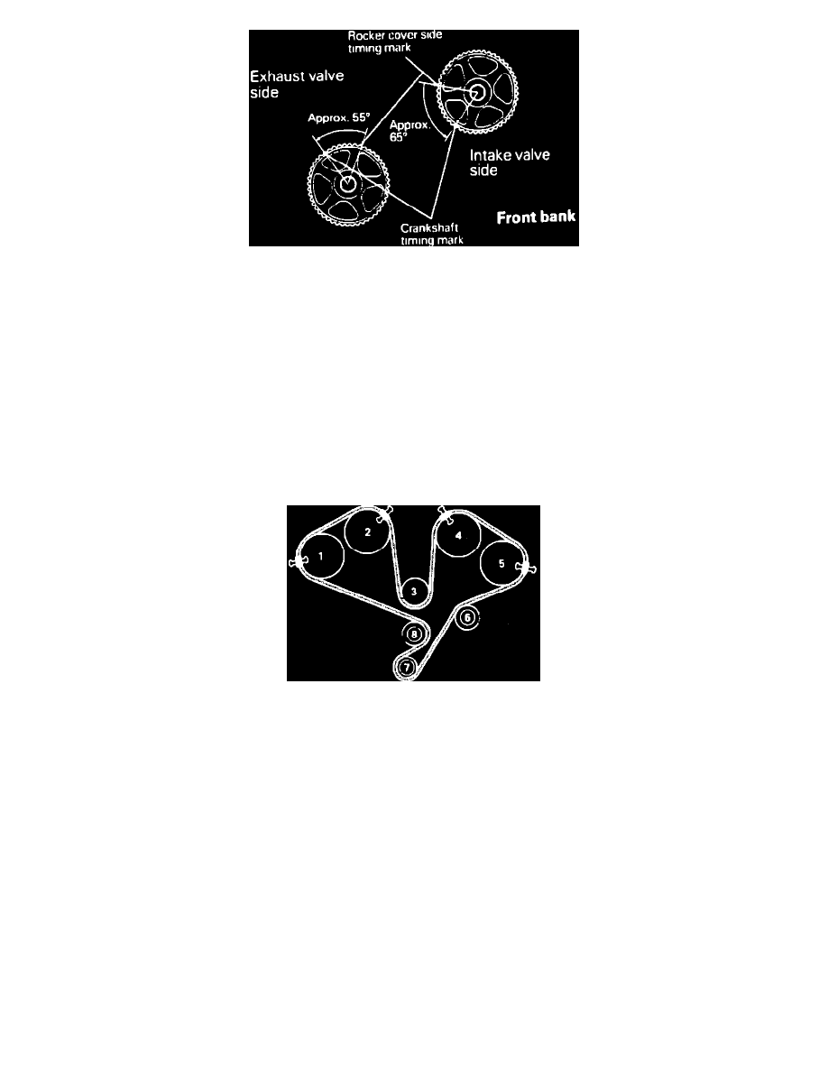
Fig. 46 Positioning Camshaft Sprockets. DOHC
6.
Align timing marks for camshaft sprockets on the front bank, as follows:
a. Install the crankshaft pulley. Shift timing mark on crankshaft sprocket by three teeth to lower piston in No. 1 cylinder slightly from top dead
center. Turning camshaft sprocket with piston in No. 1 cylinder located at TDC may cause valves to interfere with piston.
b. Make sure that timing marks on camshaft sprockets for intake and exhaust valves are not within range marked A, Fig. 45. If timing mark is
within range marked A, turn camshaft sprocket to move timing mark to area closest to range marked A. In range marked A, the cam lobe on
the camshaft lifts the valve through the rocker arm and the camshaft sprocket is apt to rotate by reaction force of the valve spring.
c. Turn camshaft sprocket to locate timing mark as shown in Fig. 46. If the intake and exhaust valves of the same cylinder lift
simultaneously, interference with each other may result. Therefore, turn the intake camshaft sprocket and the exhaust camshaft
sprocket alternately.
d. Turn camshaft sprocket clockwise to align the timing marks. If camshaft sprocket has been turned excessively, turn sprocket counterclockwise
to align timing marks.
e. Align timing mark of the crankshaft sprocket. Shift timing mark of crankshaft sprocket one tooth in counterclockwise direction to install timing
belt.
Fig. 47 Timing Belt Installation. DOHC
7.
Using paper clips to hold timing belt in place, install timing belt in order shown in Fig. 47, ensuring not to allow belt to slack.
8.
Turn tensioner pulley so that its pin holes are located above the center bolt. Press tensioner pulley against timing belt and temporarily tighten
center bolt.
9.
Ensure timing marks on all sprockets are aligned properly then remove clips.
10.
Adjust timing belt by rotating crankshaft 1/4 turn counterclockwise, then rotate it clockwise until timing marks are aligned.