
Stealth R/T V6-2972cc 3.0L DOHC (1991)
Refer the COMPONENT REPLACEMENT AND REPAIR for Throttle Body removal procedures.
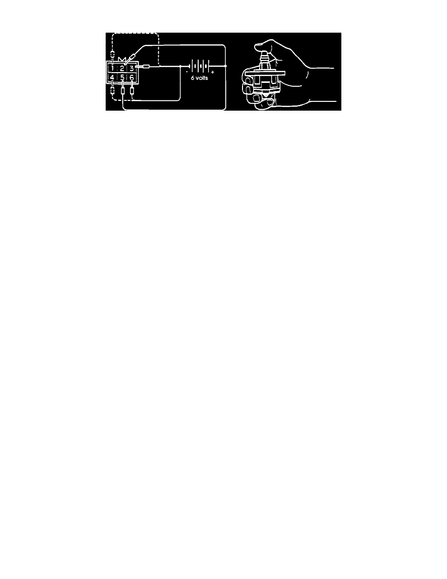
Checking The Stepper Motor Operation
2.
Connect the positive leads of a 6 volt power source to terminals # 2 and # 5 of the ISC Servo.
3.
While holding the ISC Servo, connect the negative leads of the power source to each terminal IN SEQUENCE.
A slight vibration should result at each connection.
a.
Connect the negative terminal of the power source to the ISC Servo connectors terminals # 3 and # 6.
b.
Connect the negative terminal of the power source to the ISC Servo connectors terminals # 1 and # 6.
c.
Connect the negative terminal of the power source to the ISC Servo connectors terminals # 1 and # 4.
d.
Connect the negative terminal of the power source to the ISC Servo connectors terminals # 3 and # 4.
e.
Connect the negative terminal of the power source to the ISC Servo connectors terminals # 3 and # 6.
4.
Repeat the above test procedure in reverse. Starting with step e. and ending with step a..
If vibration is felt at each step procedure, the servo can be considered to be operating normally.