
Stealth R/T V6-2972cc 3.0L DOHC (1991)
Variable Induction Control Servo: Testing and Inspection
NOTE: This system is installed on DOHC Non-Turbo equipped models vehicles.
SYSTEM INSPECTION
1.
Start and run the engine until it reaches operating temperature.
2.
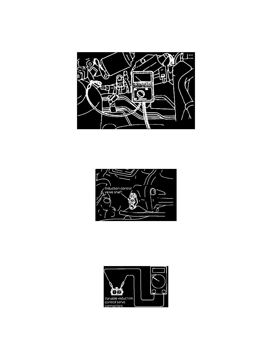
Connect a tachometer.
Tachometer Connection Using A Paper Clip
3.
Insert a paper clip into the 1-pin blue connector from the harness side. Do NOT disconnect the connector
4.
Connect a primary-voltage-detecting tachometer to the paper clip.
NOTE: The tachometer should read 1/3 of the actual engine speed. For the actual engine speed, multiply the tachometer reading by 3.
Variable Induction Control Valve Shaft
5.
Make sure that when the engine speed is increased from idle to 5,000 rpm, the induction control valve shaft turns.
SERVO INSPECTION
1.
Disconnect the variable induction control servo connectors.
VIC Servo Connector
2.
Check servos coil for continuity between terminals # 1 and # 2.
Continuity should exist.