
Stealth R/T V6-2972cc 3.0L DOHC (1991)
Power Transistor: Testing and Inspection
NOTE: The circuit tester used in the following test procedures should be an analog type.
1.
Disconnect the electrical connector to the Power Transistor.
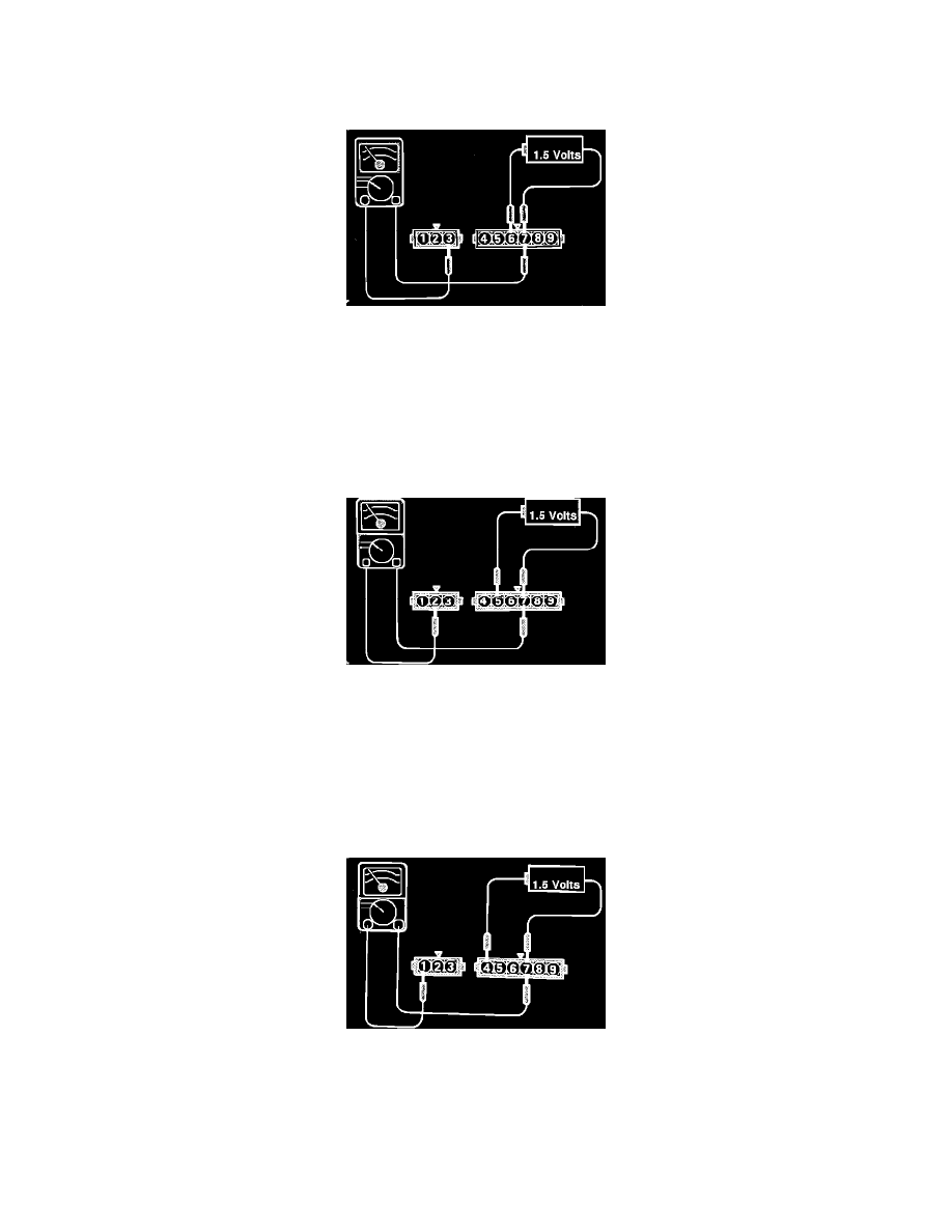
Power Transistor No. 1 Test
2.
Connect the negative lead of a 1.5 volt battery to terminal # 7 of the power transistor.
3.
Connect the positive lead of an ohmmeter to terminal # 7, and the negative lead of the ohmmeter to terminal # 3.
Continuity should NOT exist.
4.
Check for continuity when the positive lead of the battery is connected to terminal # 6 of the power transistor.
Continuity should exist, while the battery is connected.
Power Transistor No. 2 Test
5.
Connect the negative lead of a 1.5 volt battery to terminal # 7 of the power transistor.
6.
Connect the positive lead of an ohmmeter to terminal # 7, and the negative lead of the ohmmeter to terminal # 2.
Continuity should NOT exist.
7.
Check for continuity when the positive lead of the battery is connected to terminal # 5 of the power transistor.
Continuity should exist, while the battery is connected.
Power Transistor No. 3 Test
8.
Connect the negative lead of a 1.5 volt battery to terminal # 7 of the power transistor.
9.
Connect the positive lead of an ohmmeter to terminal # 7, and the negative lead of the ohmmeter to terminal # 1.
Continuity should NOT exist.
10.
Check for continuity when the positive lead of the battery is connected to terminal # 4 of the power transistor.