
Stealth R/T Turbo V6-2972cc 3.0L DOHC Turbo (1996)
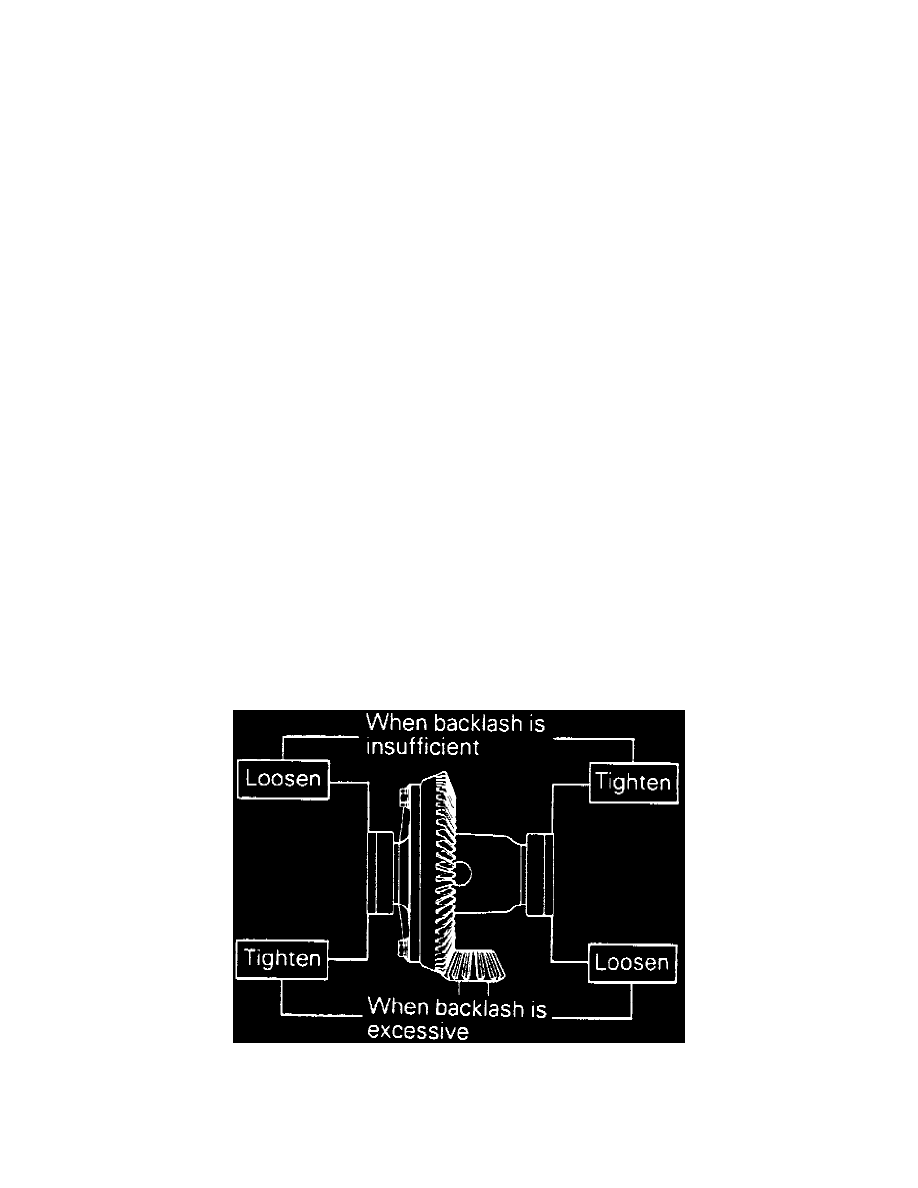
Fig.54 Rotation Torque Value
c. Measure drive pinion turning torque without oil seal installed.
d. Position gauge tube tool No. MB990392-01, or equivalent, in side bearing beat of gear carrier then select a drive pinion rear shim of thickness
which corresponds to gap between special tools.
e. Install selected shim on drive pinion and press fit rear bearing inner race using bearing installer tool No. MT215013, or equivalent.
5. Adjust drive pinion preload as follows:
a. Install drive pinion front shim(s) between pinion spacer and pinion front bearing inner race.
b. Tighten companion flange to specification using end yoke holder tool. Do not install oil seal.
c. Ensure drive pinion turning torque is as shown.
d. If drive pinion turning torque is not within specified range, adjust by replacing drive pinion front shims(s) or drive pinion spacer.
e. Remove companion flange and drive pinion.
f.
Install oil seal using suitable oil seal installation tool.
g. Install drive pinion and companion flange aligning marks made during disassembly then tighten companion flange self-locking nut to
specification.
h. Measure pinion turning torque with oil seal installed and ensure turning torque is no more than one inch lb. greater than what is shown.
6. Adjust differential gear backlash as follows:
a. Assemble side gears and spacers, pinion gears and washers into differential case.
b. Temporarily install pinion shaft.
c. While locking side gear with wedge, measure differential gear backlash with a dial indicator on pinion gear. The measurement should be made
for both pinion gears individually.
d. If differential gear backlash exceeds 0.008 inch, adjust backlash by installing thicker side gear spacers.
e. Measure differential gear backlash again and confirm it is within the specification.
f.
After adjustment, ensure backlash is less than limit and differential gear rotates smoothly.
g. When adjustment is impossible, replace side gear pinion hears as a set.
7. Align pinion shaft lockpin hole with differential case and install lockpin.
8. Stake lockpin at two points.
9. Clean drive gear attaching bolts.
10. Use a 10mm x 1.25 tap to remove adhesive from threaded holes of drive gear.
11. Install drive gear onto differential case aligning marks made during disassembly. Tighten bolts in a diagonal sequence.
12. Press side bearing inner races onto differential case.
13. Adjust final drive gear backlash as follows:
a. Using spanner wrench tool No. MB991367 and pin tool No. MB991385, or equivalents, temporarily tighten side bearing nut until just before
preloading.
b. Measure final drive gear backlash at four or more points on drive gear.
c. Using spanner wrench and pin tools, adjust backlash until a 0.004-0.006 inch value is reached by turning side bearing nut as shown.
Fig.55 Final Gear Backlash Adjustment
d. Using the spanner wrench to apply preload, turn down both right and left side bearing nuts on half the distance between centers of two
neighboring holes.